Making the first prototype of my wireless audio system using Ti's CC85XX series chips
I'll be writing this as things come, so the writing style might be a bit different.
For headphones, I own a Sennheiser HD-25. Frankly it's a superb piece, the audio is wonderful. However, I wanted for ages now to have a reliable and non-bulky way to make these headphone wireless with compromising quality too much.
I could obviously just a cheap UHF tx/rx pair but not only I would expose my audio to anyone but there would be no way to have the second feature that I wanted: a stereo back channel (or at least mono) for a microphone or line in.
After countless hours of search, let me introduce the CC85XX series, these chips from Texas Instruments are capable of juggling between 4 channels, and they work at 2.4GHz (granted the range might be reduced a bit but at least not anyone will be able to decode the audio). These chips are beasts:
I was sold, so I started to recreate the convenient application circuit of the datasheet on easyeda: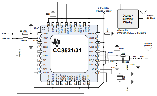
And as I wanted to be as flexible as possible I placed both the matching circuit and the CC2590 rf amp on the schematic.
After spending way too much time trying to understand how the PurePath wireless configurator worked I finally found the audio codec chip that is compatible with my needs, and so I settled for the TLV320AIC3204IRHBR this chip is equally a beast, but I had one issue:
I could not figure out how to programmatic switch between the line in and the microphone input of the chip which was somewhat problematic. Sure I could reprogram the chip each time I want to switch but that didn't seem very viable, so now I had to mess with one of the thing I dread the most: analog signals.
After quite a bit of experimentation with the chips I had (tl07x, tl08x, lm386, lm358, ne5532) I made a circuit with the tl071 which somewhat worked, however I had to max out my sound card input amp to have something useable (mind you the quality was fantastic). So clueless as I am with analog signals I went for a search on the internet and found the OPA2348 sure they were way better options, but they were also a lot more expensive (I'm looking at you MAX4466).
Conveniently the OPA2348 data sheet provides an application schematic for and electret microphone preamp circuit, so I continued the schematic by recreating the circuit, however something caught my eyes: the application schematic states a band pass of 300Hz to 3kHz which is good but not quite good enough especially in the high frequency side
I then proceeded by creating a schematic for all of this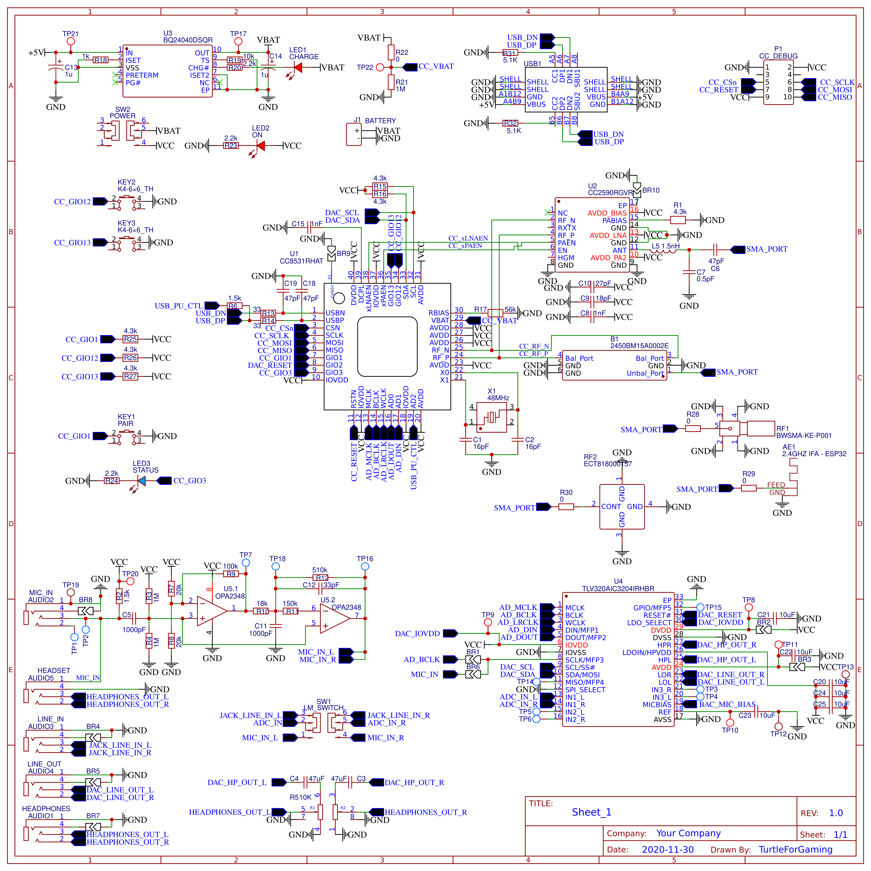
I next designed the PCB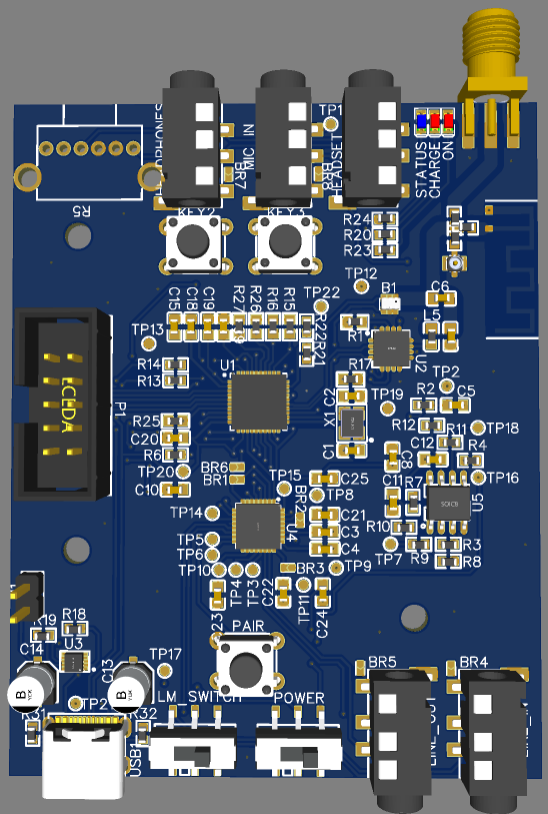
So after waiting a week for the PCB to arrive I for the first time soldered the component with solder paste. The USB-C connector was definitively the hardest to solder correctly, even now I'm not sure.
Obviously the first power up didn't work at all. Like VCC an GND shorted together. After many hours of scratching my head looking at the PCB and the schematic I could find the flaw. Turns out I might have meddled with the PCB after the order because you can see the VCC trace going straight into the ground plane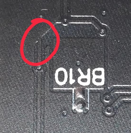
Now the only issue is that I don't have a cc-debuger, so I ordered one but the mail service here SUCKS, so I wasn't able to do anything with the PCB for around 1.5 weeks. After I received it tho I was able to use the Ti PurePath Wireless configurator to program the chip which,
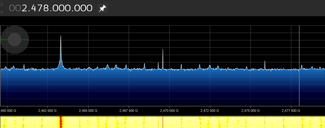
So a few weeks back I got my cc-debugger program both boards both lighted up but didn't pair. And after searching for a config option that I would have missed I kinda gave up for 2-3 days, but then I remembered that I got a hackrf that can see where the signal is and while programming both boards as masters the signal wasn't in the same place.
So I started a thread on Ti E2E forum:
As per comment #3582181 :
The first board is working fine, it was a few hundred kHz of, so I adjusted the C1,C2 caps to 24pF instead of 16pf, and it's now only 3kHz off the test frequency.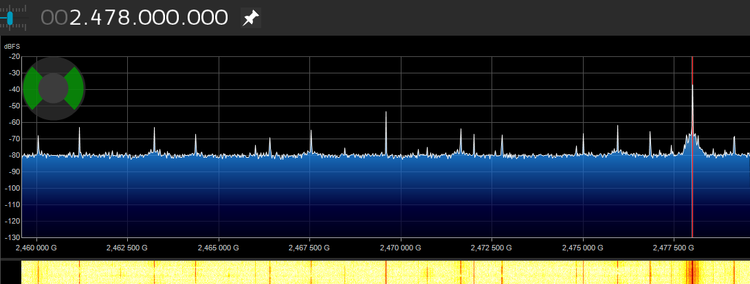
And my suspicion were right I've soldered a new CC8531, configured everything, and they paired with each other. SUCCESS
Well not yet, they paired without any issues and I even managed to use the remote control option and control my computer volume however there was no sound to be heard
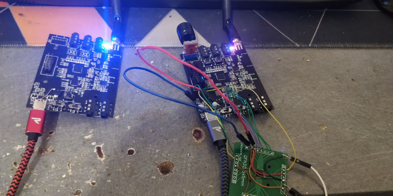
So make it easier to debug I soldered a TLV320AIC3204 to a QFN breakout board, painfully soldered jumper wires to the PCB pads and to the breakout board. I then started probing with my oscilloscope and sure enough there was no data on the I2S data lines, the clocks were working fine tho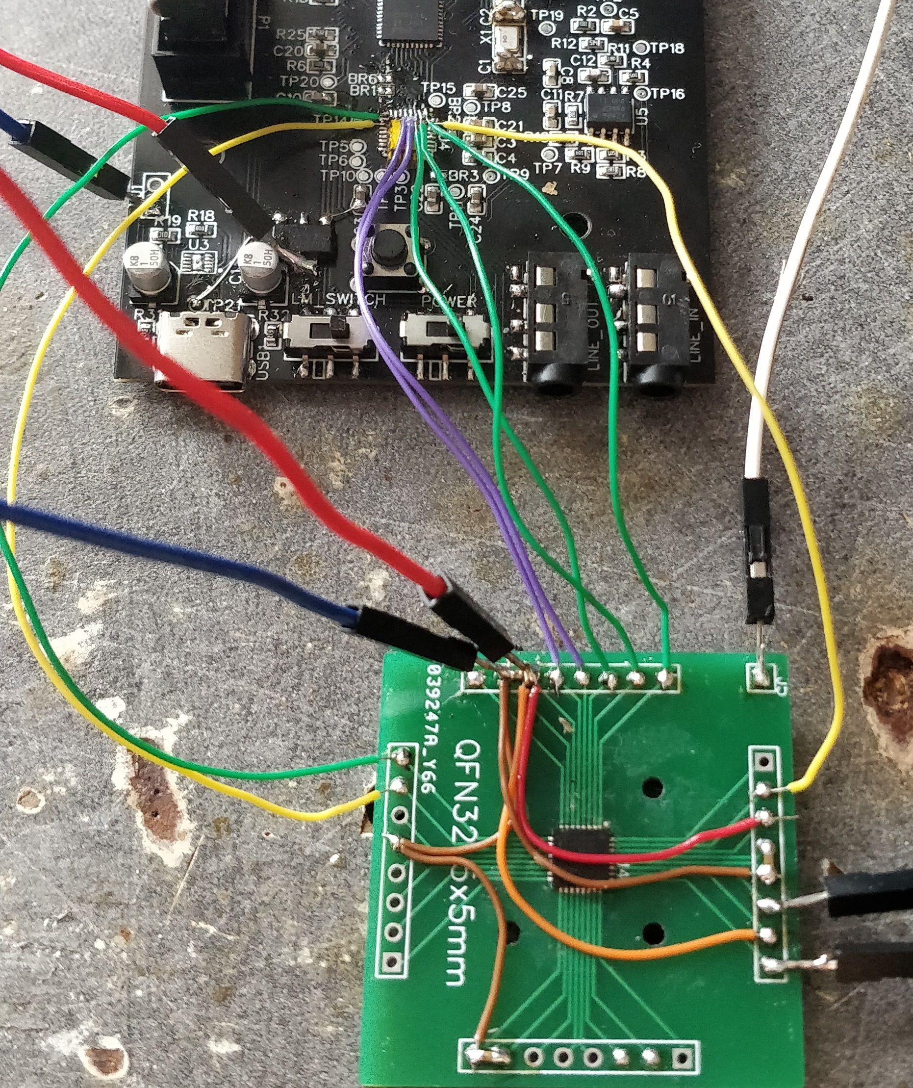
After more probing I managed to see that the codec chip was configured correctly since it outputted data:
As it turns out the guy who help me couldn't find an issue with my schematic and directed me toward a config issue. After discovering that there was preconfigured examples of project files and after doing a bit of tweaking to said files, I managed to get a 2 channel stereo link. Yay.
After much tinkering with the config file I was able to add a third channel for a microphone, and it worked. Not well, the audio cut a lot (tho I manged to keep it stable for 5min) but it showed that it was possible.
I suspect that a lot of my issues are related to my poor PCB design and component choices for the rf parts that's why I'm currently recreating a schematic for a new prototype, and I'll hopefully don't make any big mistakes. I'll do another blog post about it whenever I get finished everything
Want to chat about this article? Just post a message down here. Chat is powered by giscus and all discussions can be found here: TheStaticTurtle/blog-comments