The adventure of rendering SVGs with KiCad pcbnew python api.
What I wanted to do was pretty simple, at least I thought, I wanted to replicate the comportment of the "Export → SVG" button in KiCad.

What I wanted to do was pretty simple, at least I thought, I wanted to replicate the comportment of the "Export → SVG" button in KiCad.
Pretty easy no? Load the board, create a plot controller change a few options, and we're ready. And this where it went haywire:
 1import pcbnew
 2filename = "board.kicad_pcb"
 3output_dir = "output/"
 4board = pcbnew.LoadBoard(filename)
 5plot_controller = pcbnew.PLOT_CONTROLLER(board)
 6plot_options = plot_controller.GetPlotOptions()
 7plot_options.SetOutputDirectory(output_dir)
 8plot_options.SetPlotFrameRef(False)
 9plot_options.SetDrillMarksType(pcbnew.PCB_PLOT_PARAMS.FULL_DRILL_SHAPE)
10plot_options.SetSkipPlotNPTH_Pads(False)
11plot_options.SetMirror(False)
12plot_options.SetFormat(pcbnew.PLOT_FORMAT_SVG)
13plot_options.SetSvgPrecision(4, False)
14plot_options.SetPlotViaOnMaskLayer(True)
15plot_controller.OpenPlotfile("mask", pcbnew.PLOT_FORMAT_SVG, "Top mask layer")
16plot_controller.SetColorMode(True)
17plot_controller.SetLayer(pcbnew.F_Mask)
18plot_controller.PlotLayer()
19plot_controller.ClosePlot()
Multiple issues with this:
SetColorMode set to True, there isn't any colour hereThis, is in retrospect, pretty easy to fix but a nightmare to find.
The pcbnew lib exposes the ComputeBoundingBox function and (luckily) the EDA_RECT class.
To get the center point for the board, we can do:
1pcb_bounding_box = board.ComputeBoundingBox()
2print("origin", pcb_bounding_box.GetOrigin())
3print("height", pcb_bounding_box.GetHeight())
4print("width", pcb_bounding_box.GetWidth())
Then we can enable the use of the auxiliary origin and set it to the origin of the pcb bounding box:
1plot_options.SetUseAuxOrigin(True)
2board.GetDesignSettings().SetAuxOrigin(pcb_bounding_box.GetOrigin())
First issue solved
Thanks to the bounding box from the first issue, we know exactly what size the output should, so let's change it.
According to the documentation, the BOARD class has a function called GetPageSettings and I know from reading the source code, that GetPageSettings returns a pointer to a PAGE_INFO class that holds the page size. So one would think that we could do something like this (at least that's what is done in the GUI code when you click "Export → SVG"):
1currpageInfo = board.GetPageSettings()
2currpageInfo.SetWidthMils(int(pcb_bounding_box.GetWidth() / pcbnew.IU_PER_MILS))
3currpageInfo.SetHeightMils(int(pcb_bounding_box.GetHeight() / pcbnew.IU_PER_MILS))
4board.SetPageSettings(currpageInfo)
But no, no, no, the PAGE_INFO class doesn't have a swig proxy in the pcbnew file, so you actually can't modify it. You can use it, but cannot call or access anything inside (the only statements posing an issue are SetWidthMils and SetHeightMils)
Traceback (most recent call last):
File ".\main.py", line 60, in generate
 k = generator.generate(options.canvas, options.color, **options.options)
File ".\generators\spotify\main.py", line 281, in generate svgs = pcb2svg.generate_svg_from_gerber_and_drill(kicad_pcb_file.name, theme=color)
File ".\tools\kicad\pcb2svg.py", line 281, in generate_svg_from_gerber_and_drill
 currpageInfo.SetWidthMils(int(pcb_bounding_box.GetWidth() / pcbnew.IU_PER_MILS)) AttributeError: 'SwigPyObject' object has no attribute 'SetWidthMils'
So, how do you bypass that? By modifying the exported SVG, of course.
Looking at an SVG generated by the GUI, we can deduce the values that would actually need replacing from the bounding box
python IU_PER_MM = pcbnew.IU_PER_MILS / 2.54 * 1000 VIEW_BOX_DIVIDER = 100  # Why that value? Wish I knew
new_svg_attributes = {
    "width": f"{round(pcb_bounding_box.GetWidth() / IU_PER_MM, 5)}cm",
    "height": f"{round(pcb_bounding_box.GetHeight() / IU_PER_MM, 5)}cm",
    "viewBox": f"0 0 {int(pcb_bounding_box.GetWidth() / VIEW_BOX_DIVIDER)} {int(pcb_bounding_box.GetHeight() / VIEW_BOX_DIVIDER)}",
}
Thereafter, we can use python XML library to properly edit the attributes of the SVG (i.e., not a brute force .replace)
1import xml.etree.ElementTree as xml_et
2tree = xml_et.parse("output/board-mask.svg")
3root = tree.getroot()
4for attr, value in new_svg_attributes.items():
5    root.attrib[attr] = value
6    svg = xml_et.tostring(root, encoding='utf8', method='xml')
7    print(svg)
And success we now have a black & white SVG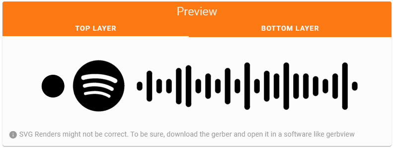
You would think that using SetColorMode(True) would actually enable colours. Why would that be the case, though? Why would it be easy?
As with the first issue, it's in retrospect a pretty easy fix.
Turns out that you need to tell the thing to use the damn default colour scheme because why a default colour scheme would be used by default.
1settings_manager = pcbnew.GetSettingsManager()
2color_settings = settings_manager.GetColorSettings()
3plot_options.SetColorSettings(color_settings)
Success we now have ugly colours but at least they are there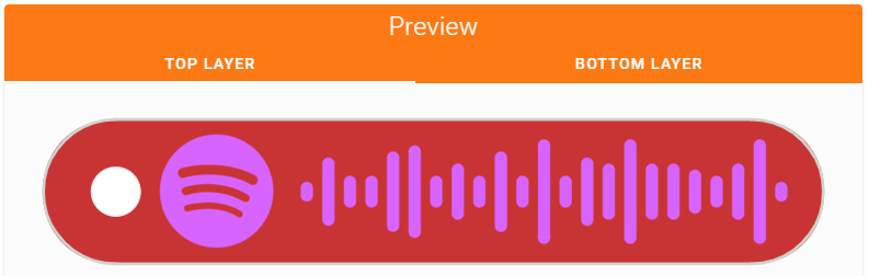
Once again, one would think that we could use the color_settings var to change the colours, but that would be too easy. The COLOR_SETTINGS class doesn't have a swig proxy in the pcbnew, either. Great.
So to modify the colours, we need to pull out the big guns and use .replace on the SVG to get colour that are somewhat OK.
After a bit of poking around in the SVG, the colour are these (didn't bother with the silkscreen for now):
1KICAD_THEME_SEARCH = {
2 "top_silkscreen": "-----unknown-----",
3 "top_mask": "D864FF",
4 "top_layer": "C83434",
5 "edge_cuts": "D0D2CD",
6 "bottom_layer": "C83434",
7 "bottom_mask": "D864FF", "bottom_silkscreen": "-----unknown-----",
8 "drill": "ECECEC",
9}
We can then use a bit of code to replace everything:
 1top_layer = top_layer\
 2 .replace(KICAD_THEME_SEARCH["top_silkscreen"].encode("utf8"), theme["top_silkscreen"].encode("utf8"))\
 3 .replace(KICAD_THEME_SEARCH["top_mask"].encode("utf8"), theme["top_layer"].encode("utf8"))\
 4 .replace(KICAD_THEME_SEARCH["top_layer"].encode("utf8"), theme["top_mask"].encode("utf8"))\
 5 .replace(KICAD_THEME_SEARCH["edge_cuts"].encode("utf8"), theme["edge_cuts"].encode("utf8"))\
 6 .replace(KICAD_THEME_SEARCH["drill"].encode("utf8"), theme["drill"].encode("utf8"))
 7bottom_layer = bottom_layer\
 8 .replace(KICAD_THEME_SEARCH["bottom_silkscreen"].encode("utf8"), theme["bottom_silkscreen"].encode("utf8"))\
 9 .replace(KICAD_THEME_SEARCH["bottom_mask"].encode("utf8"), theme["bottom_layer"].encode("utf8"))\
10 .replace(KICAD_THEME_SEARCH["bottom_layer"].encode("utf8"), theme["bottom_mask"].encode("utf8"))\
11 .replace(KICAD_THEME_SEARCH["edge_cuts"].encode("utf8"), theme["edge_cuts"].encode("utf8"))\
12 .replace(KICAD_THEME_SEARCH["drill"].encode("utf8"), theme["drill"].encode("utf8"))
You can note that, as the mask layer isn't actually a mask layer but only a layer, I need to invert top_mask and top_layer. It isn't great but works for now as I wanted to avoid dealing with it any more.
And finally, we have our SVG (rendered with the black ENIG theme)
This may appear elementary, but doing things without any proper docs and with APIs that lacks some features can take quite a while. Getting to this state took at somewhere between 8 and 10 hours of reading the documentation, reading the source code and trial & error.
I have great respect for the KiCad devs and while it might look a lot like a rant towards KiCad, it is not.
I realize that generating SVG from the python API probably isn't the principal use of the lib.
In my opinion, an API layer should either expose everything that need to access what the API is for or should not exist, no in-between. A few parts don't have a swig proxy and are a pain to get around. I would also have expected a better doc of the api from such a big project.
But then again, KiCad is free and open-source you can't rant at the devs (or anything really). If I had more time, I could implement it and ask to merge it upstream and solve it for everyone, however I do have a life.
Want to chat about this article? Just post a message down here. Chat is powered by giscus and all discussions can be found here: TheStaticTurtle/blog-comments