Building a DIY CO2 and PM2.5 sensor to measure the air quality in my office and improve my home-maker life.
As I spend most of my day in my office 🤓, I thought it would be a good idea to measure the CO2 levels of the room. CO2 isn't as dangerous as CO, but it can still pose some issues if the levels are too high. And after being in a room that hasn't any ventilation for +10h straight, the CO2 level is definitely high.
This study, found that the level of CO2 has a very negative effect on performance, particularly on thinking in general:
I also wanted to measure the PM2.5 concentration, as it could prove useful for automations down the road.
My office does have a window and, in summer, it's pretty easy, as I leave it open all the time. In winter, however, the room gets cold quickly. Which is why I wanted a sensor that can tell me if I need to open the window.
So, what's available out there? Well, first of, I want something that won't send everything to some cloud that I don't control. That reduce the options quite a bit.
IMO, the Aranet4 from Aranet is the best sensor if I wanted something pre-made. Looks very well-made and is compatible with HomeAssistant. However, it's pretty pricey.
As I also wanted to measure the quantity of particulates floating in the air and I couldn't find a sensor that measured both that was at low enought price.
It meant DIY 🧐!
First, what do I actually need. I already have temperature and humidity from a Mi-Thermometer, I don't care much about the light level. What I do care about is:
After reading a few blog posts and watching a few videos, I choose to use the MH-Z19, it can measure the CO2 concentration in ppm from 0 to 5000ppm and the temperature and output it to either serial or PWM. Seems perfect for my needs.
For the particulate matter sensor, I choose a PMS5003 which gives me PM2.5, PM1.0 and PM10
I first hoped into SolidWorks and my something that reassembles a case.
The PMS5003 has an intake fan in it and by default the air is ejected on the same side:
So, here is what I came up with:
The air comes in from the side, ejected on the other side and then passes over the MHZ19.
On the front, I added a recess for a washer that I'll use a button using the esp32 touch library, a recess for the OLED and a hole for LEDs:
On one side I added an intake hole for the fan, an output, and a hole for the USB wire.
Assembly was a little finicky. I started by inserting the OLED:
Then poured hot glue in the LED hole to act as a diffuser and then put the LED strip in:
Unfortunately, my 3D print wasn't perfect and the PM5003 didn't fit by less than a millimeter. So, I used some hot air to ease it in 😏:
Then with a lot of patience, I manage to solder everything to the ESP32 and hot glued it in place:
A bonus of the 3D print being slightly out of size, is that I can use the flat side of the PMS5003 to stick it to the wall with some double side tape.
Usually, I would write my own firmware for the ESP32 that would publish the sensor data to my MQTT server and I would create the entities myself in HomeAssistant.
However, this time I chose to use ESPHome because it's way easier to use and integrates perfectly with HomeAssistant.
So let's get started. First thing to do is to set up esphome:
 1esphome:
 2  name: office-air-quality
 3
 4esp32:
 5  board: esp32dev
 6  framework:
 7    type: arduino
 8
 9logger:
10
11api:
12  encryption:
13    key: "FTt4GyAtVoM8tIqBhNSW3QF+SND9NaIA97l1FkfTdGg="
14
15ota:
16  password: "8ebf931b96986fa4d46fb35987957b3d"
17  id: my_ota
18
19wifi:
20  ssid: !secret wifi_ssid
21  password: !secret wifi_password
22  ap:
23    ssid: "Office-Air-Quality"
24    password: !secret ap_password
25
26captive_portal:
Next is the interface setup, I need the two UARTs for the pms5003 and mhz19, the I2C for the OLED, the touch interface for the button and the fonts for the OLED
 1i2c:
 2  - id: i2c_oled
 3    sda: 18
 4    scl: 19
 5
 6uart:
 7  - id: uart_pms5003
 8    rx_pin: GPIO16
 9    tx_pin: GPIO17
10    baud_rate: 9600
11  - id: uart_mhz19
12    rx_pin: GPIO26
13    tx_pin: GPIO25
14    baud_rate: 9600
15
16esp32_touch:
17  setup_mode: false
18
19font:
20  - file: "gfonts://Lato"
21    id: lcdfont_big
22    size: 15
23  - file: "gfonts://Roboto"
24    id: lcdfont_small
25    size: 12
26  - file: "gfonts://Roboto"
27    id: lcdfont_verysmall
28    size: 10
Then I need to add the sensors, fortunately ESPHome has platforms for the pms5003 and the mhz19. As I use an ESP32, I can also use the esp32_touch platform for the user button.
 1sensor:
 2  - platform: pmsx003
 3    uart_id: uart_pms5003
 4    type: PMSX003
 5    pm_1_0:
 6      id: pmsx003_pm1_0
 7      name: "Concentration particules <1.0µm"
 8    pm_2_5:
 9      id: pmsx003_pm2_5
10      name: "Concentration particules <2.5µm"
11    pm_10_0:
12      id: pmsx003_pm10_0
13      name: "Concentration particules <10.0µm"
14  - platform: mhz19
15    uart_id: uart_mhz19
16    co2:
17      id: mhz19_co2
18      name: "Capteur CO2"
19    temperature:
20      id: mhz19_temp
21      internal: true
22    update_interval: 30s
23    automatic_baseline_calibration: false
24
25binary_sensor:
26  - platform: esp32_touch
27    internal: true
28    name: "Button"
29    pin: GPIO27
30    threshold: 1000
31    on_press:
32      - display.page.show_next: oled
Next are the outputs, I used a small OLED with 3 pages with the only thing changing being the PM2.5 / PM1.0 / PM10, CO2 is always displayed. And the light with the internal key to hide it from HomeAssistant.
 1display:
 2  - platform: ssd1306_i2c
 3    id: oled
 4    model: "SSD1306 128x32"
 5    address: 0x3C
 6    pages:
 7      - lambda: |-
 8          it.print(0, 0 , id(lcdfont_big), "CO2  ");
 9          it.print(0, 15, id(lcdfont_big), "PM2.5");
10          it.print(54, 1 , id(lcdfont_small), String((int)(id(mhz19_co2).state)).c_str());
11          it.print(54, 17, id(lcdfont_small), String((int)(id(pmsx003_pm2_5).state)).c_str());
12          it.print(92, 3 , id(lcdfont_verysmall), "ppm");
13          it.print(92, 18, id(lcdfont_verysmall), "ug/m3");
14      - lambda: |-
15          it.print(0, 0 , id(lcdfont_big), "CO2  ");
16          it.print(0, 15, id(lcdfont_big), "PM1.0");
17          it.print(54, 1 , id(lcdfont_small), String((int)(id(mhz19_co2).state)).c_str());
18          it.print(54, 17, id(lcdfont_small), String((int)(id(pmsx003_pm1_0).state)).c_str());
19          it.print(92, 3 , id(lcdfont_verysmall), "ppm");
20          it.print(92, 18, id(lcdfont_verysmall), "ug/m3");
21      - lambda: |-
22          it.print(0, 0 , id(lcdfont_big), "CO2  ");
23          it.print(0, 15, id(lcdfont_big), "PM10");
24          it.print(54, 1 , id(lcdfont_small), String((int)(id(mhz19_co2).state)).c_str());
25          it.print(54, 17, id(lcdfont_small), String((int)(id(pmsx003_pm10_0).state)).c_str());
26          it.print(92, 3 , id(lcdfont_verysmall), "ppm");
27          it.print(92, 18, id(lcdfont_verysmall), "ug/m3");
28
29light:
30  - id: status_led
31    internal: true
32    platform: neopixelbus
33    variant: WS2811
34    pin: GPIO33
35    num_leds: 9
36    type: GRB
Thankfully, esphome automatically updates the OLED content. Which is not the case of the LEDs, so I used the SNTP platform to execute a script every 1 second.
The script does the following:
 1time:
 2  - platform: sntp
 3    on_time:
 4      - seconds: /1
 5        then:
 6          - lambda: |-
 7              LightCall status_led_call = id(status_led).turn_on();
 8
 9              status_led_call.set_state(true);
10              status_led_call.set_transition_length(100);
11
12              if(id(mhz19_co2).state >= 1500) {
13                status_led_call.set_rgb(0.392, 0.015, 0.588); // Purple
14                status_led_call.set_brightness(1.00);
15              } else  if(id(mhz19_co2).state >= 1200) {
16                status_led_call.set_rgb(0.921, 0.000, 0.000); // Red
17                status_led_call.set_brightness(0.75);
18              } else  if(id(mhz19_co2).state >= 900) {
19                status_led_call.set_rgb(0.620, 0.392, 0.000); // Orange
20                status_led_call.set_brightness(0.27);
21              } else if(id(mhz19_co2).state >= 650) {
22                status_led_call.set_rgb(0.031, 0.690, 0.007); // Green
23                status_led_call.set_brightness(0.18);
24              } else {
25                status_led_call.set_rgb(0.007, 0.600, 0.749); // Blue
26                status_led_call.set_brightness(0.15);
27              }
28
29              status_led_call.perform();
Flashed the compiled esphome firmware and was greeted by some wonderful logs:
[20:43:27][D][pmsx003:236]: Got PM1.0 Concentration: 3 µg/m^3, PM2.5 Concentration 4 µg/m^3, PM10.0 Concentration: 4 µg/m^3
[20:43:28][D][mhz19:057]: MHZ19 Received CO₂=693ppm Temperature=24°C Status=0x00
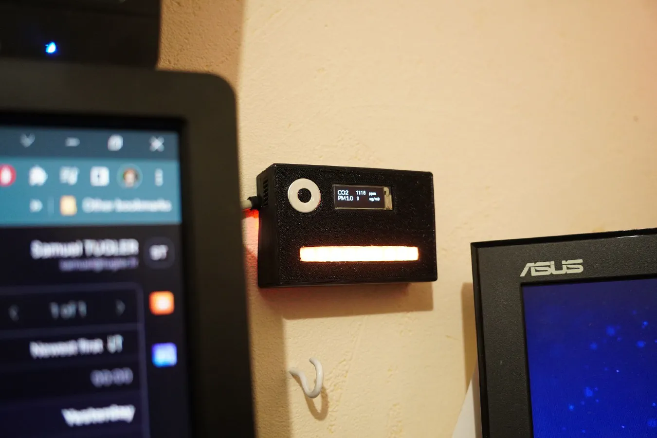
The LEDs and OLED lighted up with the correct info:

I added the entities in HomeAssistant, left it for a while and got these wonderful graphs:

Overall, I'm pleased with this project, I didn't take very long to make, it's not too big, it's not really distracting unless the level is too high. It's going to be a really useful tool for long programming or soldering sessions.
Want to chat about this article? Just post a message down here. Chat is powered by giscus and all discussions can be found here: TheStaticTurtle/blog-comments