Creating a microphone holder with tally lights for a live show and integrating it to the MIDAS M32 mixing console
This is a stupidly long article, it details the concept, design, and construction phases thoroughly, you'll need probably more than 45 min to really read it
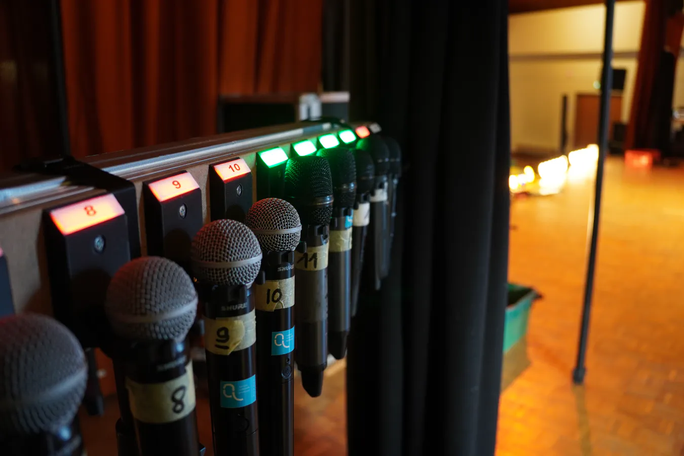
Every once in a while, I work in my local choir. Every few years, they do a tour singing music for around 3h. This year there are more than 25 singers and 15 microphones. Add microphones for the drums, bass, guitar, saxophone, trumpet, ..... and you reach the maximum 32 channels of our MIDAS M32 console quite fast.
You may notice that 25 is greater than 15 🤔, that's because we have one or two techs who hand out the mics according to the all mighty “mic-sheet”.
Basically, this sheet is a grid of every song and every microphone with the performer's name if they need one. It gets fine-tuned over time during rehearsals so that when the first real concert comes, the mic transitions between performers are as smooth as possible. This is fine and worked for over a decade, but we are still human and sometimes mistakes happen. For example, someone might grab the wrong mic and go on stage, or maybe the microphone has become magically invisible 👻.
Combine that with my love for problem-solving 🤓, and I decided that I would do a system that can do multiple things:
One problem that could still happen is that someone could put the wrong microphone in the wrong holder, we would have no way of knowing which one is the right one. But my guess is that it's more likely that the mics run out of battery than someone misreading two numbers (one on the mic and one on the holder) 🤷♂️.
I thought about using RFID tags on each mic to solve the "wrong holder" issue, and that would indeed make sure that the right microphone is in the proper holder. But, that brings me to the 2nd thing that this project needs to be: cheap! 💰 The thing is that I'm doing everything myself and don't want to spend 20 EUR per holder, especially knowing that one could break in the chaos of the backstage. No, I want it to be as cheap as possible.
But, I still need to have 15 of them connected to a controller capable of talking to the M32.
That took some though 🤔 as I originally wanted to do use a single bus or a daisy-chaining approach, where all holders would have an IN and an OUT port to simplify wiring.
Single bus/daisy-chaining for the LEDs is easy, a few WS2812B in each holder will do just fine, and they already work with daisy-chaining ✅.
The input for the microphone detection was a bit trickier though, I first looked at one wire IO extenders like the DS2408 or the DS2413, but they are respectively 8 EUR and 3 EUR for a single chip in the quantities I need. Far too expensive 💸. At the same time I started this project, I had an ongoing PCB order, I thought that I could potentially put a full RP2040 block in each holder, but that would also be 2 - 5 EUR per holder in the quantities I require.
So short of doing some analog trickery to make the thing work on one wire 😐, I said f- that and committed to a star topology. That means I have to bring a cable from the controller to each holder that contains these signals:
The LED out of each holder is wired to the LED in of the next one, and the "Microphone detection" button goes to a GPIO of the controller.
The first thing anyone would think of is a simple switch. While that could work, being on a budget also means that we don't have the same microphone, some are smaller than others, and I wanted to avoid doing two weeks of cad to try to make a holder compatible with everything (especially since I didn't even have access to the microphones at the start).
The second option I thought of 💡 is an IR proximity sensor. Those are also pretty cheap, 15eur for a pack of twenty is pretty good. So, I went ahead and ordered a pack, I could always find a use for it elsewhere if it didn't work out.
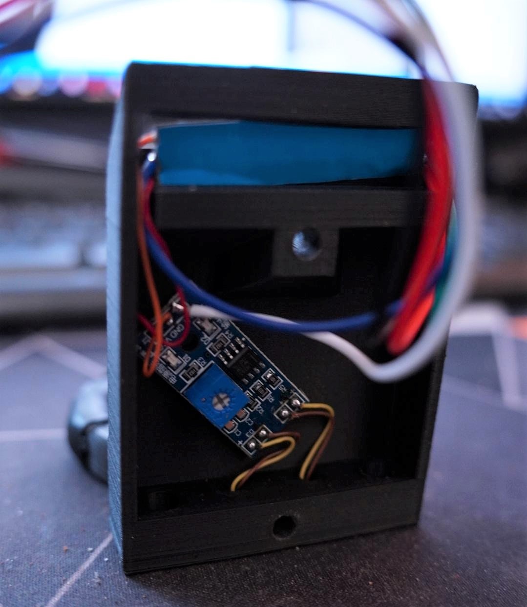
Once I got them I discovered a fatal flaw in my plan, the microphones are black and round ⚫ which doesn't really reflect the light from the sensor very well if at all. After some thinking and even trying to go back to the switch option, I realized the detection could be "normally closed" and use the microphone to block the path of the IR beam instead of reflecting it.
Perfect, I now have a cheap way of determining whether the microphone is in the holder or not 👍.
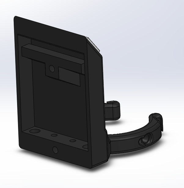
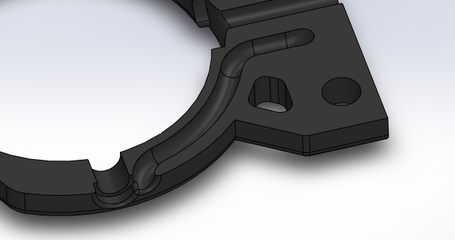
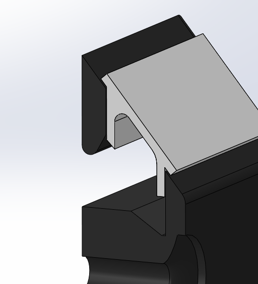
I still needed an actual solid piece of plastic to hold the microphone. The holder needs to satisfy these requirements:
After some revisions (some of which happened while I was already printing) 🤫, I ended up with this design which is printed upright in two parts (holder and led diffuser):

The LEDs are inserted in the sidearms, in retrospect, it would probably have been better to order modules with 3 mm LEDs instead of 5 mm ones since they stick out a bit, but it doesn't need to be perfect, it just needs to work. It's going to get beat up anyway 🙄. The cable for the LEDs get routed in a small channel in the arm, which then comes out in the back, where I can put the rest of the components.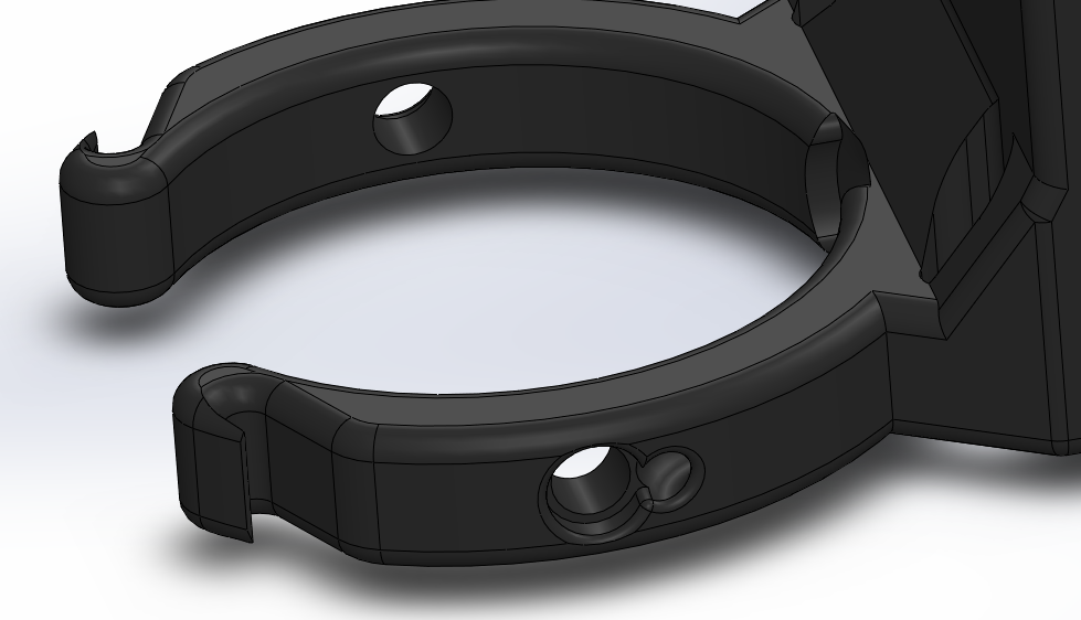
To make it easier to build the 16 modules, I chose to use a classic LED strip, I cut out 6 LEDs and jammed them in a little recess that I put in the design.
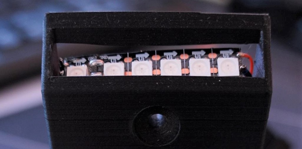
Finally, the PCB of the IR module gets attached with a piece of double-sided tape on the back and everything gets soldered together.
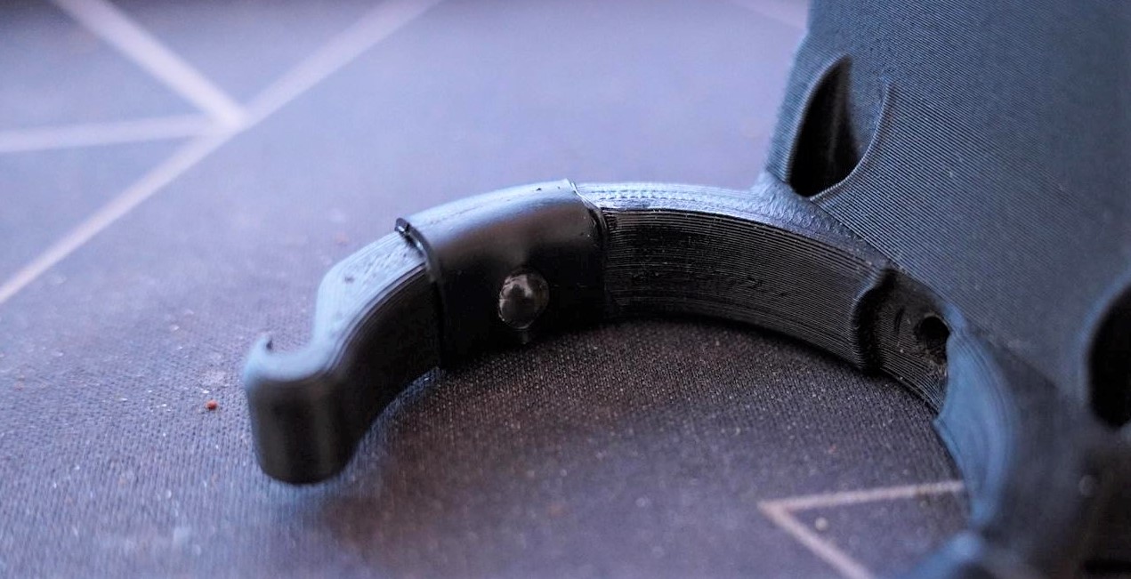
I then spent 4 days printing everything (I printed 4 modules at the same time, which kept the printer busy for around 18h 😴). The assembly was actually straightforward once I got the hang of it, but I'm glad it's done.
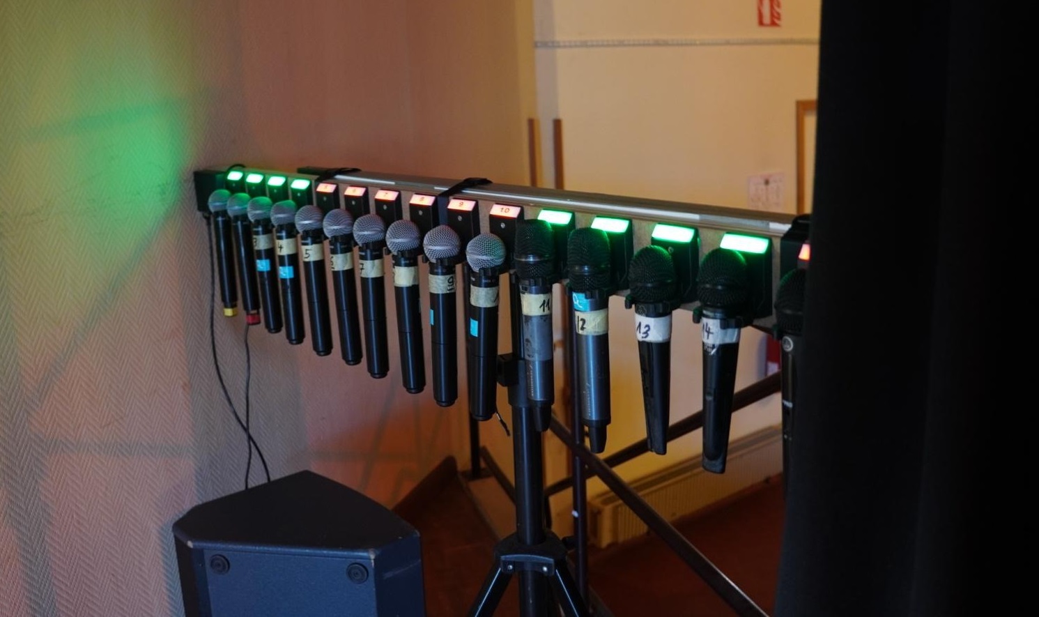
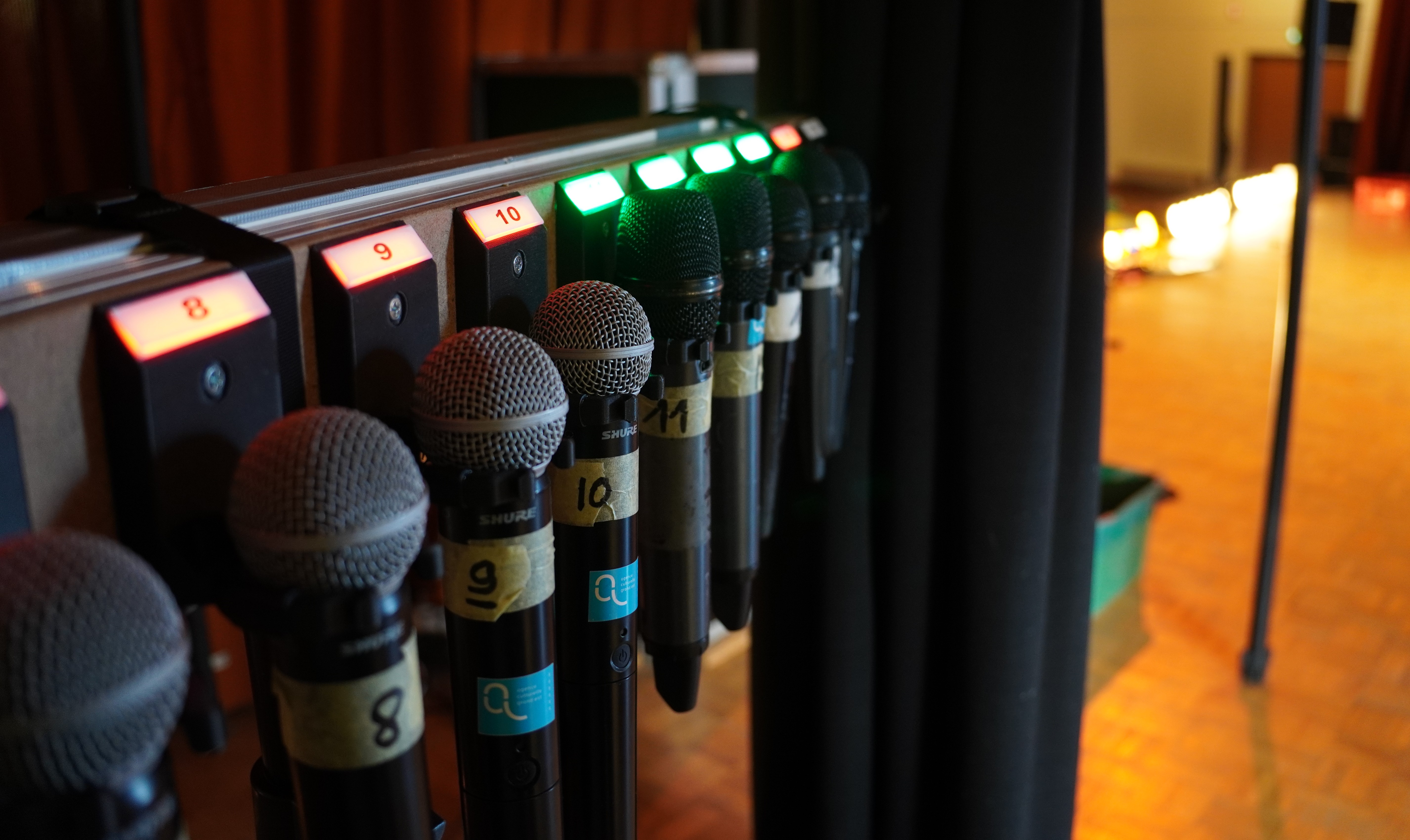
Now that everything is assembled, I printed some LED diffusers and stuck some labels with the microphone number printed on it: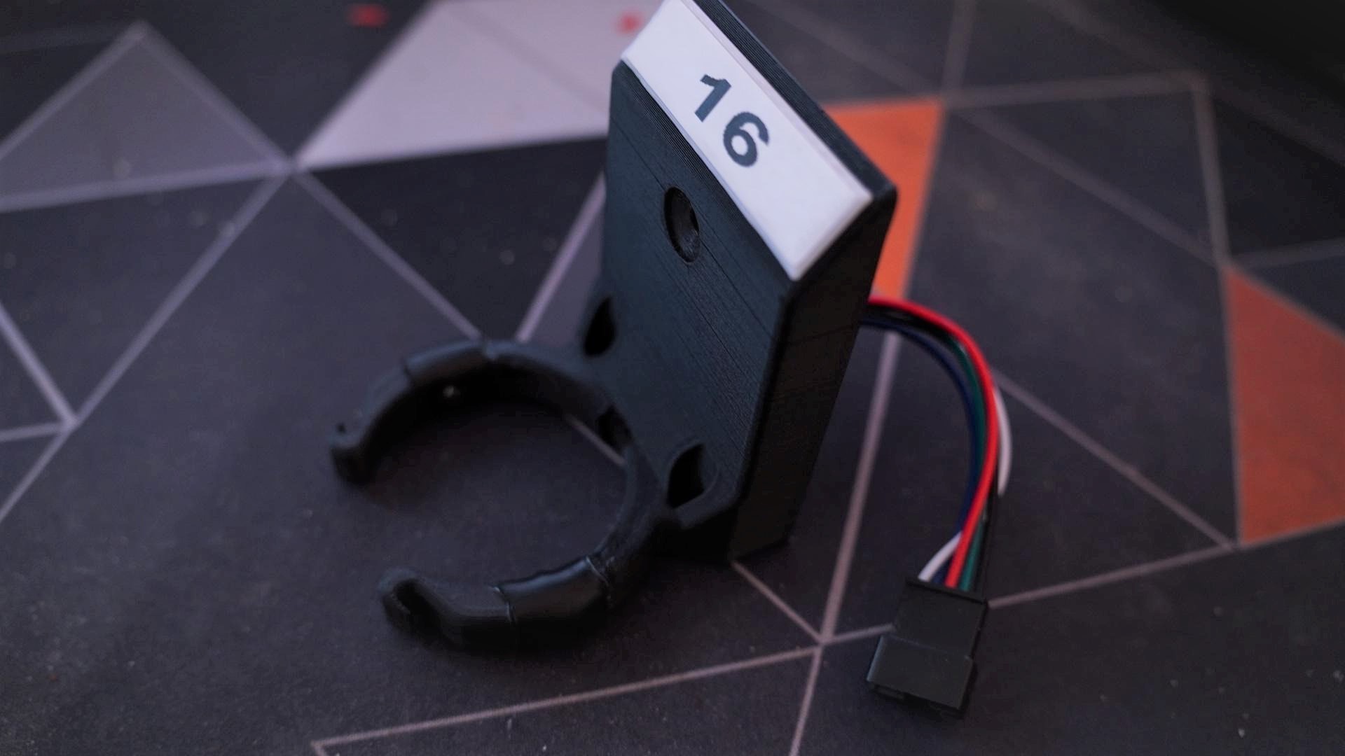
If I were to re-design this, I would probably do the following:
This would make the holder slimmer and sturdier. It might even be possible to print this hypothetical version in metal.
Originally, I wanted to have a cable going out the bottom of each holder with the JST connector and the same cable going to the controller. That would have resulted in a big mess of cables, especially at the start 😵.
Once everything was printed, we began shopping for a piece of wood that could holder everything. By pure luck, we found a U-Shaped channel of MDF that would be:

So, my dad and I started by drilling the two screw holes for each holder, plus a 20 mm hole for the cable to pass to the back. We choose to leave 2.5 cm of space between each holder to leave enough room to grab the mic easily, and something like 15 cm of space on each side for the controller.
Unfortunately, the +2 m piece of MDF wasn't very stiff, and the thing was flapping like crazy 🤔. I'll come back to that. To pile up on the bad news, the screws we chose were a bit too long by something like 5 mm.
Fortunately, we found some aluminum channels that are 20 mm deep and the perfect width. These aluminum extrusions are typically used on the side of flight cases. Mine looks a bit like this one:
https://www.thomann.de/fr/adam_hall_6102_schliessprofil.htm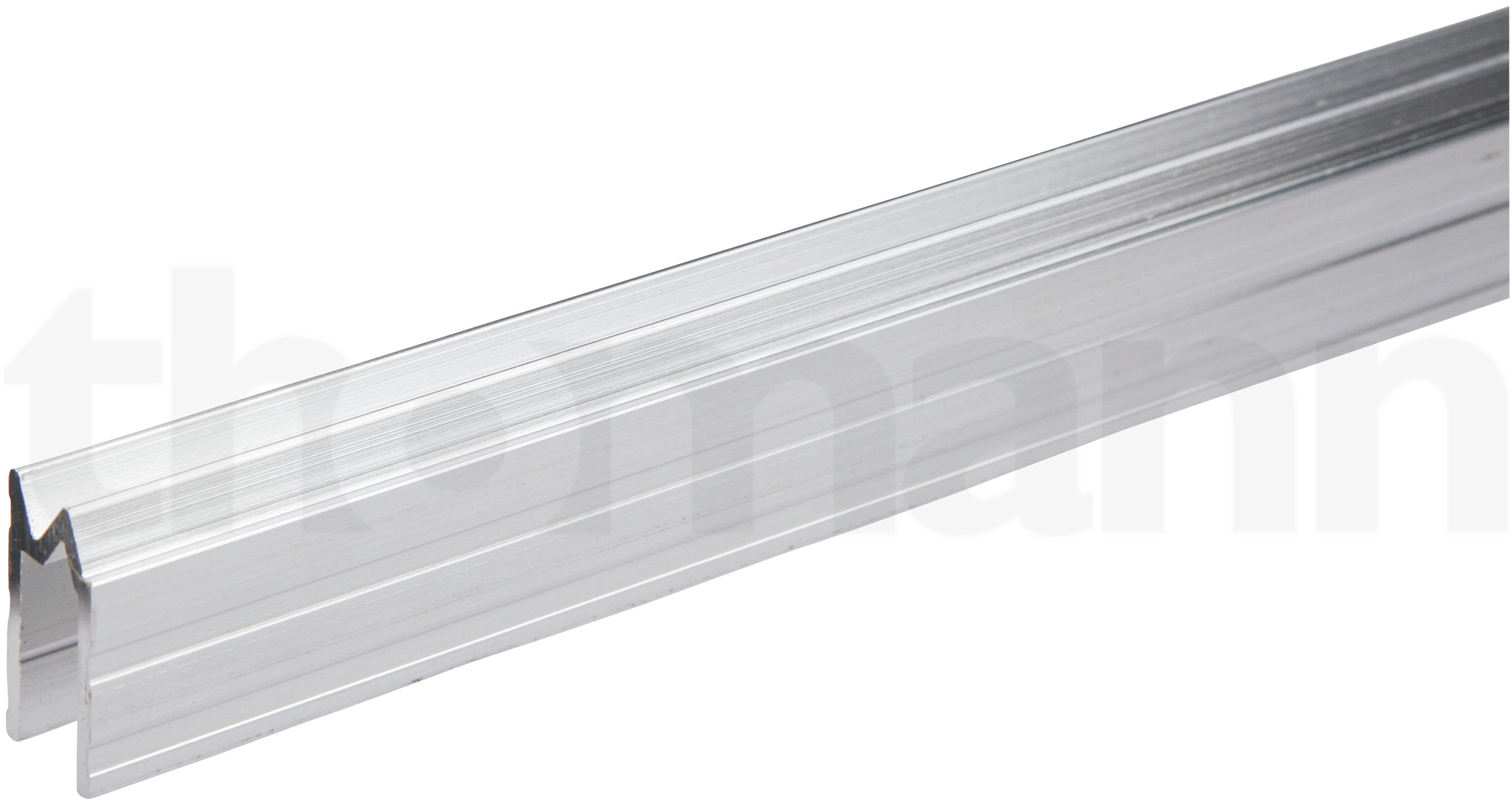
It was perfect 😄. The board looks super nice, the screws are not too long any more and as the bonus, the board is super stiff now: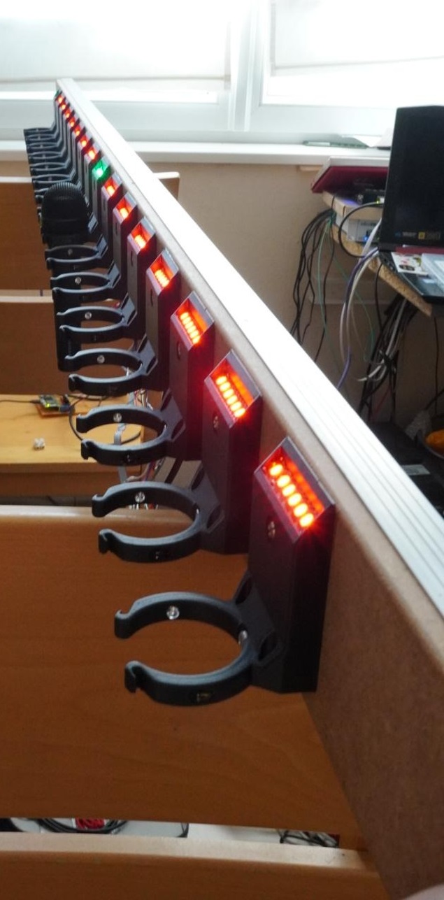
You can see that the bottom screw is barely short enough, but it will actually be very helpful later to hold the cable harness 😏: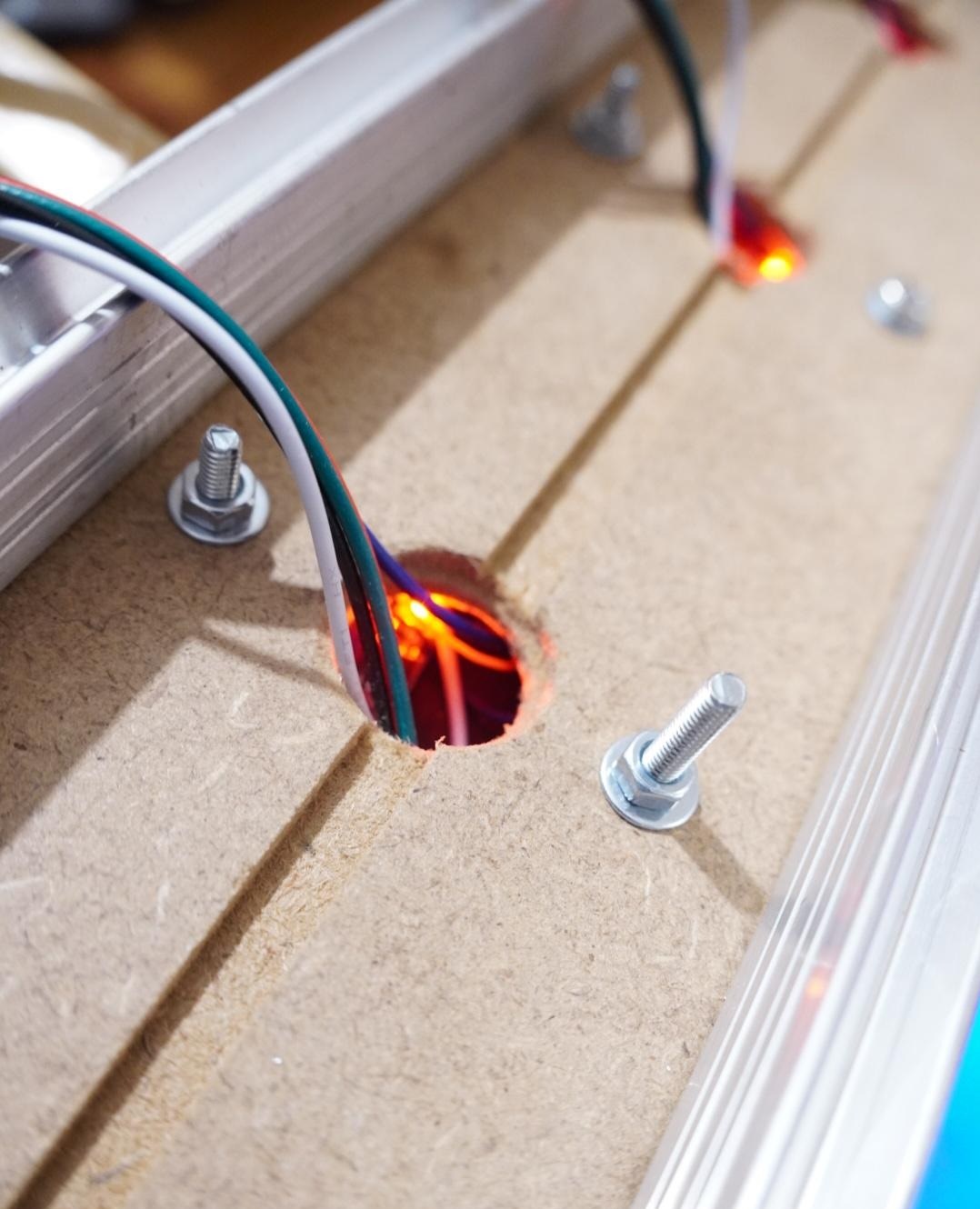
I then proceeded by cutting a ton of wires for power distribution and for the addressable LEDs data line 😫. Instead of soldering everything manually, I choose to use these wonderful heat shrink pieces that already have some solder in them: https://fr.aliexpress.com/item/1005003878417358.html.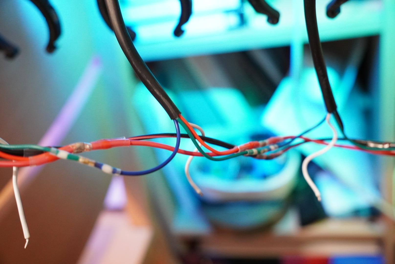
The white cable you can see is the connection of the IR module. To connect this one, I cut a 16 conductor by +2 m long piece of ribbon cable, separated the cable where required and soldered the same heat shrink pieces everywhere.
This made for a very nice cable harness to put in the back (The photo is missing the ribbon cable) 👍.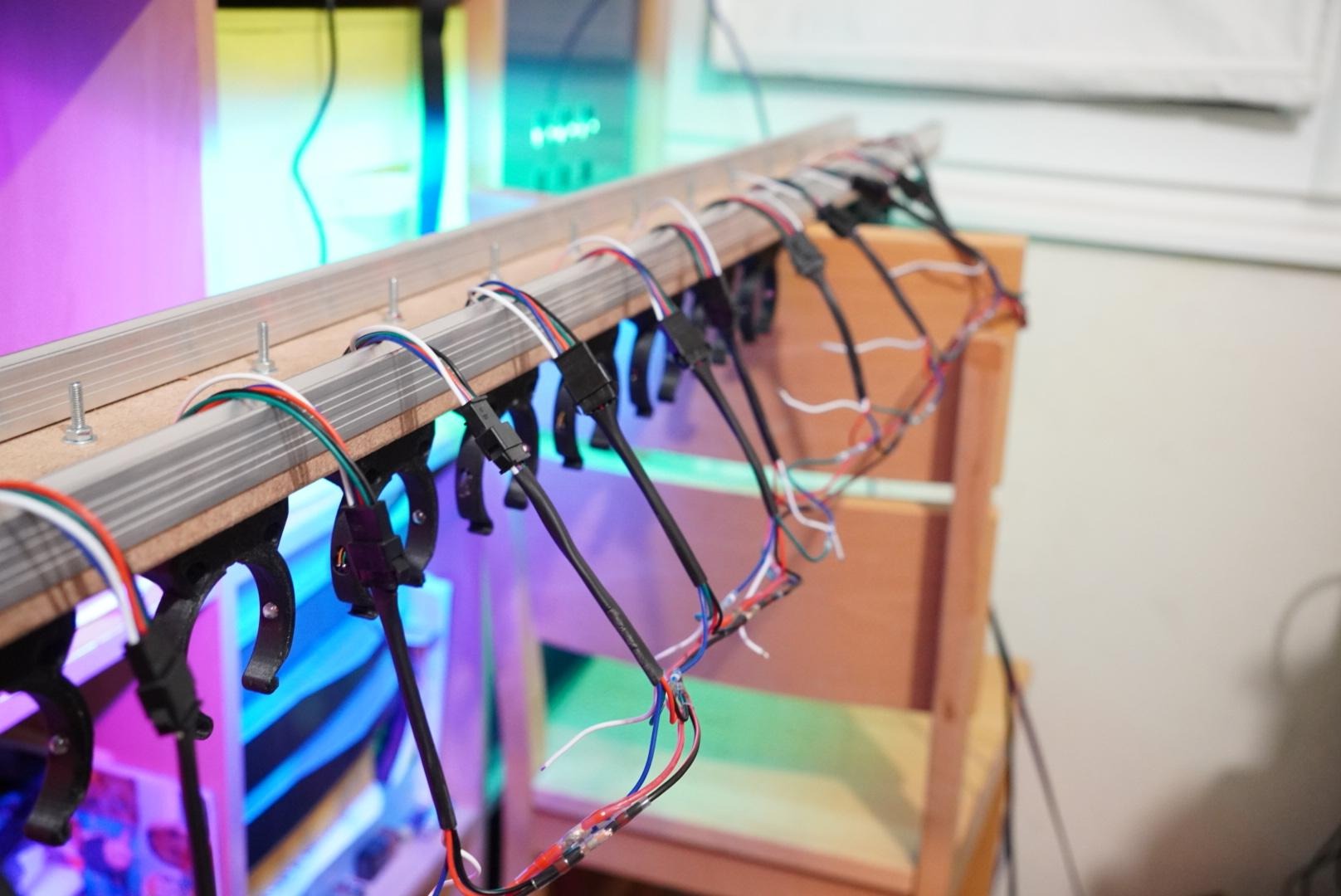
To fix everything in place, I printed some big washer that I placed on the screw post of the holder with the cable underneath. After that was done, everything was nice and neat: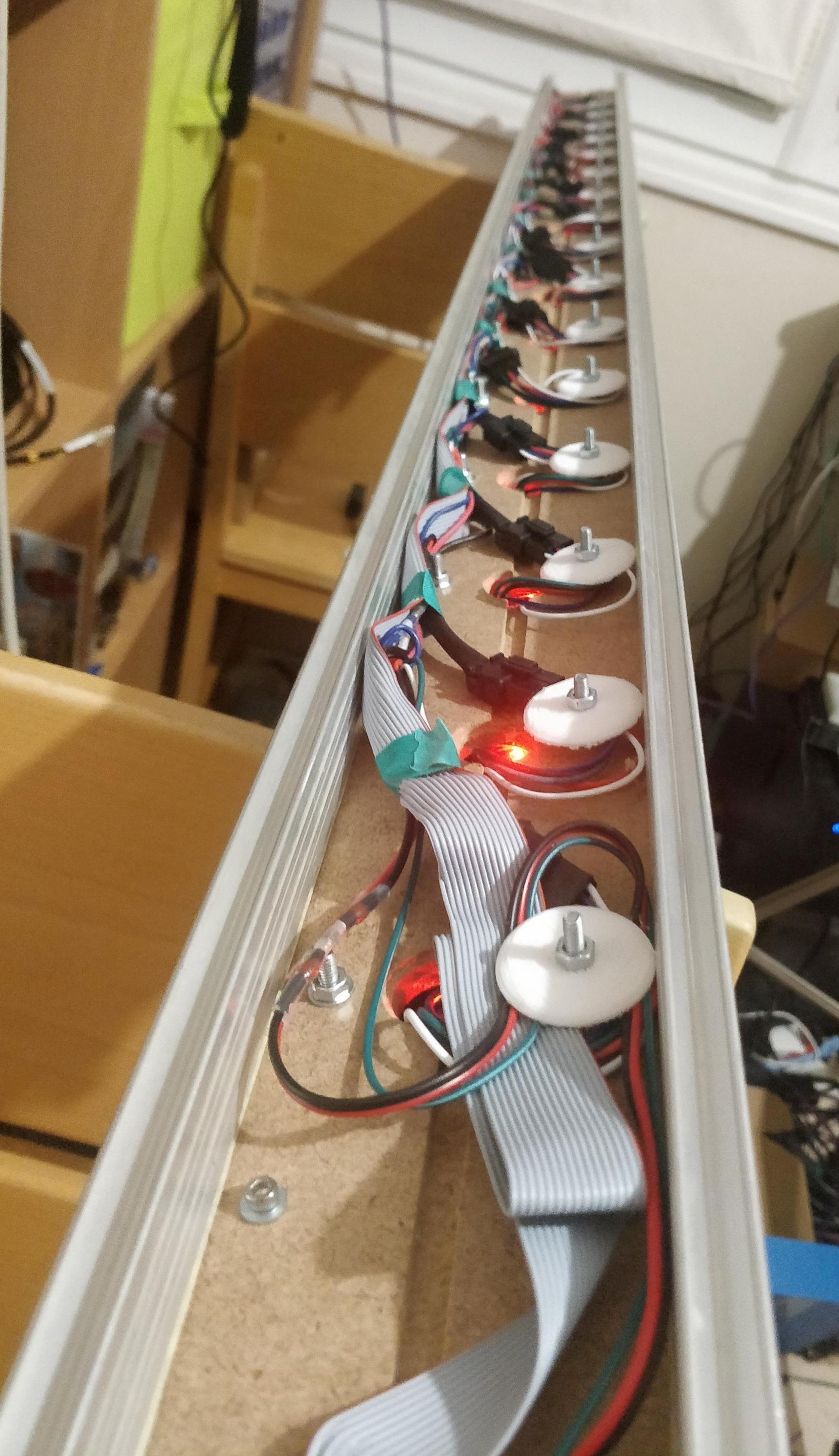
Now that I have 15 holders and a spare, I need something to control them. Originally, I wanted to use an ESP32 and fully integrate everything.
The controller needs to be able to do a few basic things:
Alongside that, a few other things need to be considered when being in a "pro" context:
That meant Wi-Fi was out of the question because there are too many issues when numerous people are connected, and I don't have the time/budget to set up a proper Wi-Fi network 📡.
Fortunately, we already have a wired network planned, which means: let's go with Ethernet.
I actually figured out quickly how to get Ethernet working on the ESP32. While I did make some progress fairly fast, I figured that I couldn't reach the required stability and reliability level by the start of the first concert. It's just too much work to re-implement everything manually for a quick project.
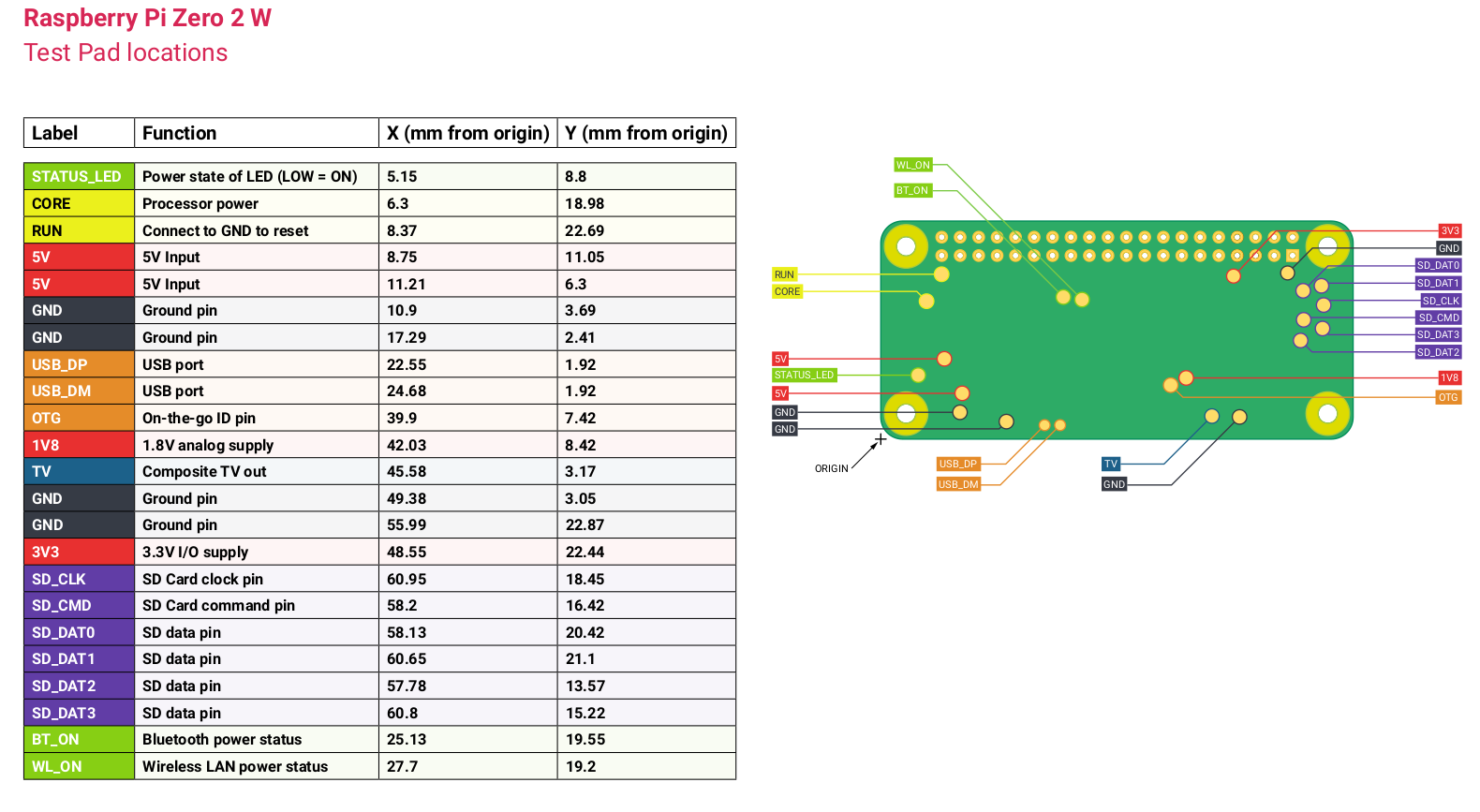
So, I dug out a now very rare PI Zero 2, and decided that I was going to use it 🤷♂️.
At first, I thought of a whole plan to use IO extender to read all the inputs. Then I looked closely at the PI and I realized that the thing has GPIO, I never used them to the point where I just forgot that they existed 😓.
A minimal issue is that my signal from the holders are +5V, and I need them to be ≤3.3V. This can be taken care of with a resistor divider, I chose 10K/10K because that's all I had in hand, which gave me 2.5V, not quite 3.3V but still above the threshold, perfect 👍.
Well, there is not a lot to say here. The ws2812b is a single pin, so I just used one that was available and called it a day 😅
I have some cheap Ethernet dongles. I cut one up and soldered it up to the D+/D- test pads of the PI Zero, that gives me Ethernet connectivity
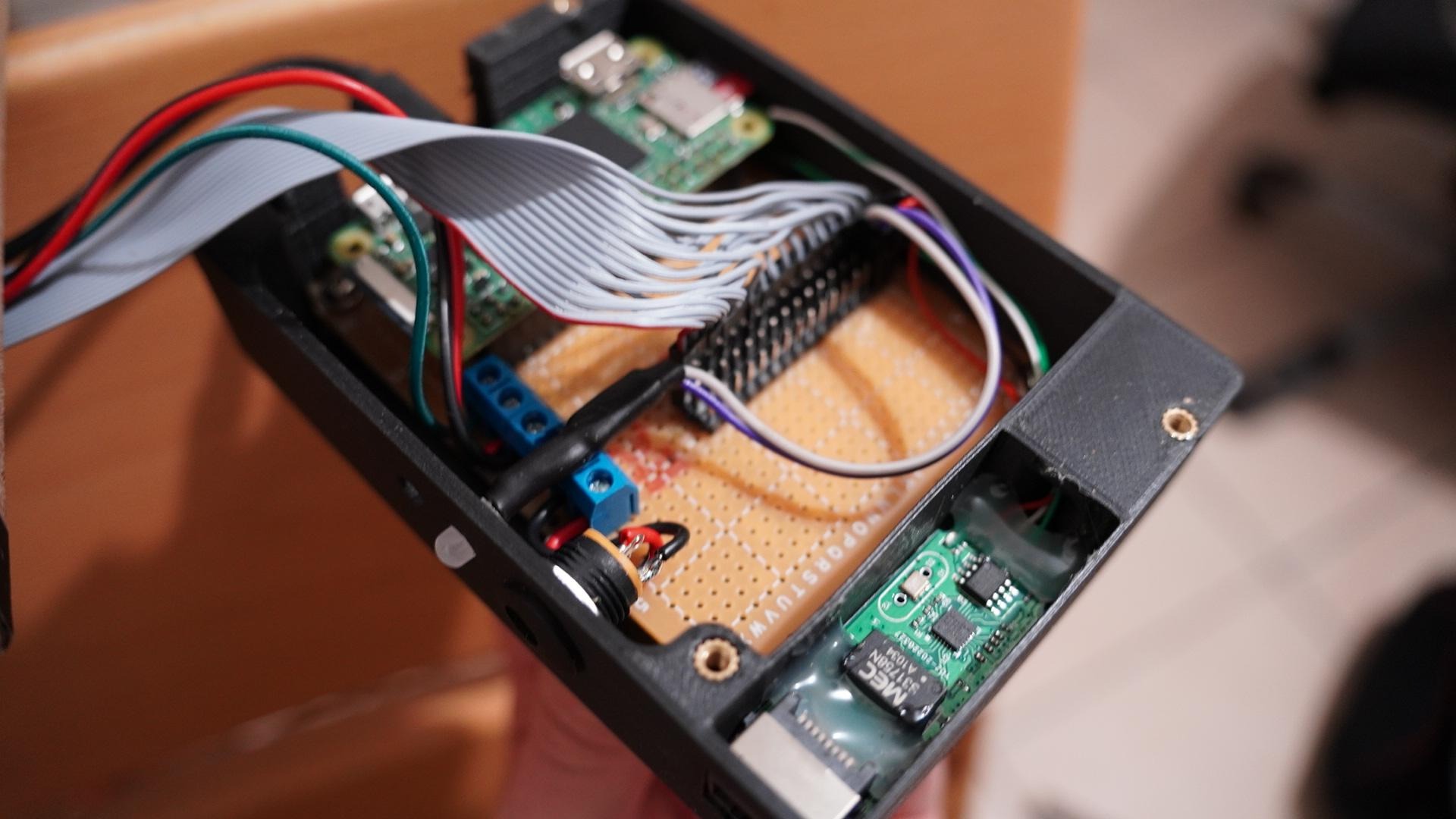
To make things easier, I decided that I would use a PCB. The issue is that, again, that I needed this thing as soon as possible ⏱, so I can't do a pre-made PCB and wait a week for shipping. I decided that I would, instead, use a perfboard and do some manual soldering.
There really isn't a lot to say, I soldered in some headers, the resistors for the dividers and some terminal blocks for power and the LEDs data.
I also soldered some DuPont connectors to the D+ and D- of the Raspberry Pi for the Ethernet card instead of using a USB to OTG adapter.
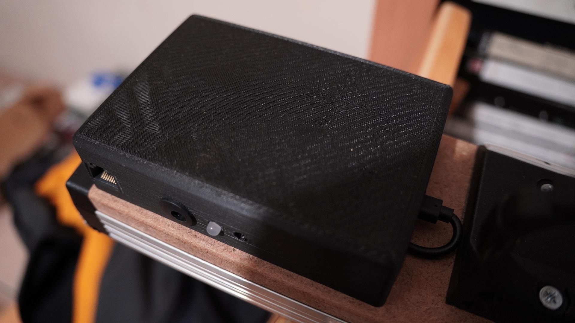
I spent some time making the PCB and the Raspberry Pi fit inside a very basic box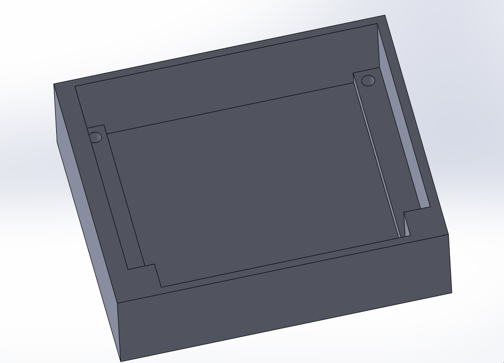
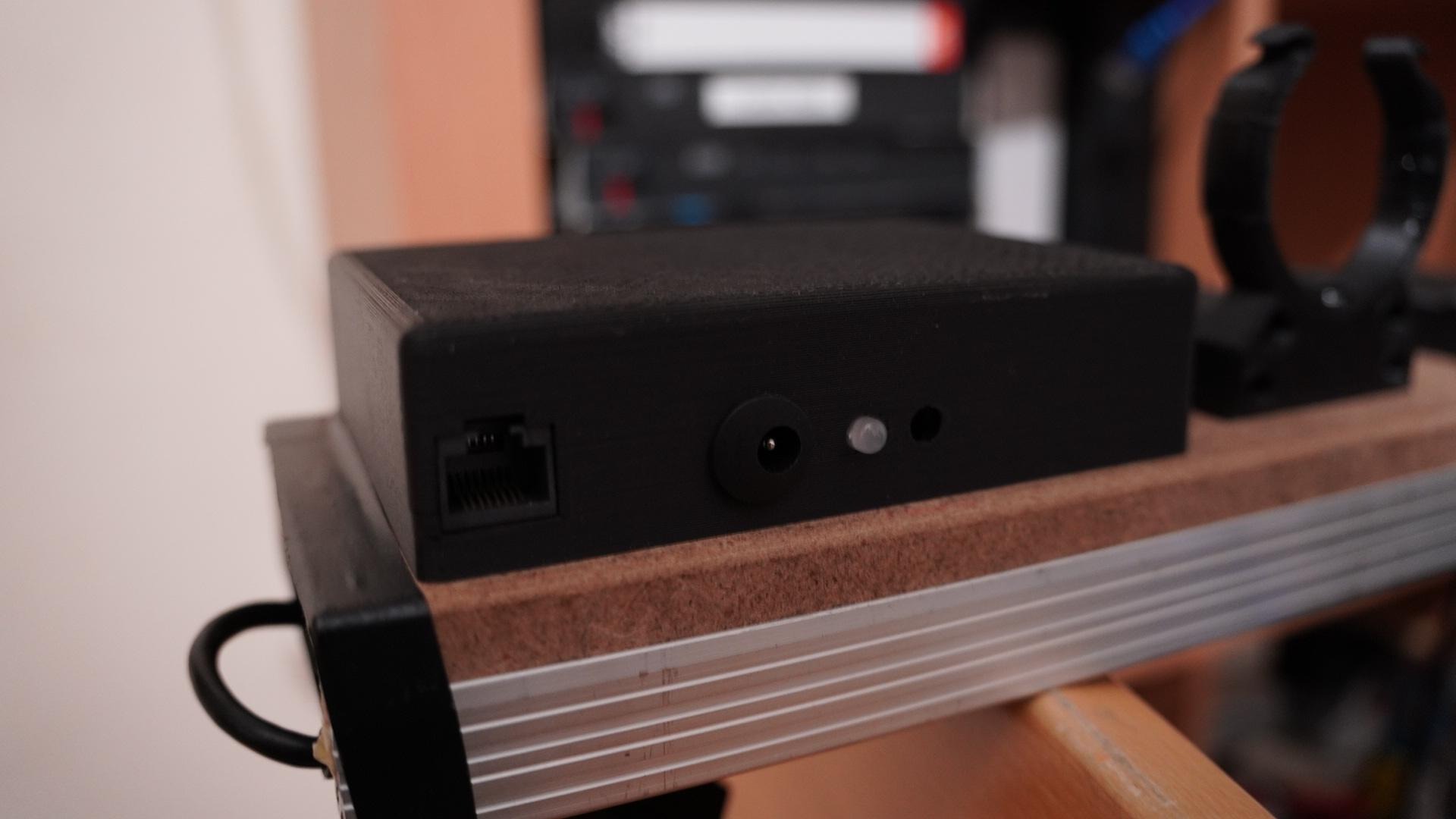
Added some holes for power, and status LEDs: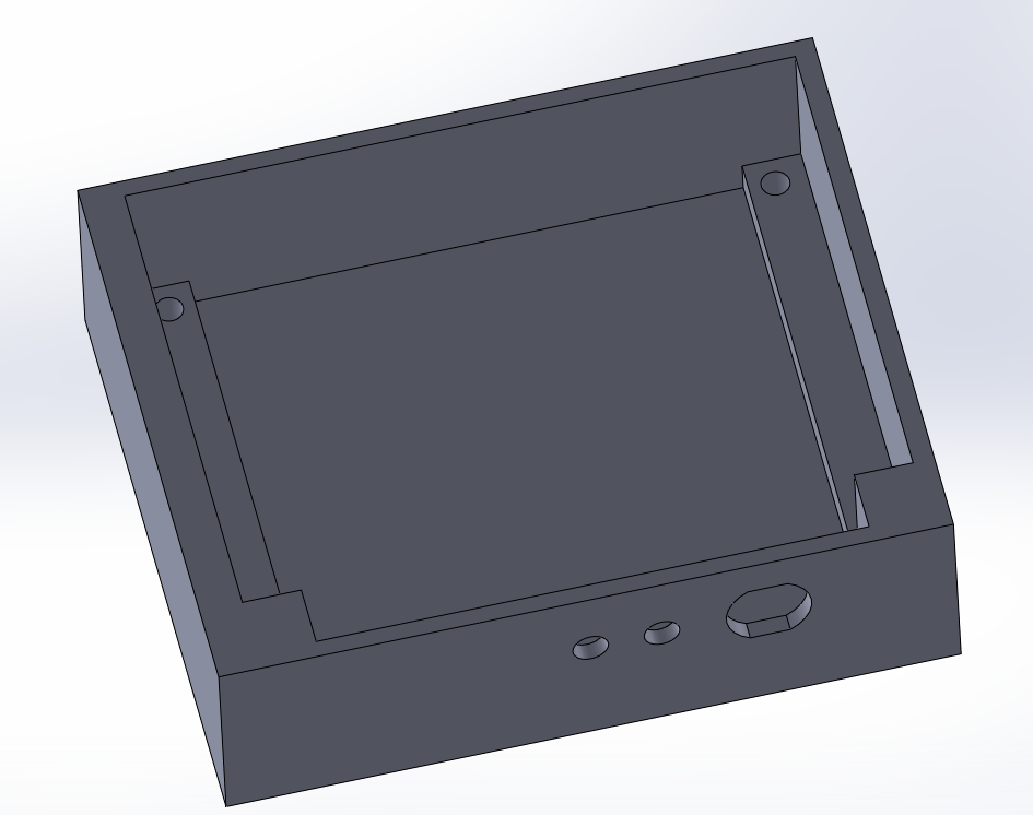
I then added a place for the network card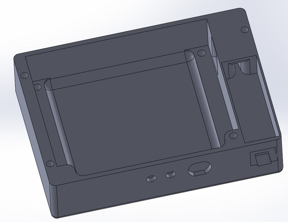
Once that got printed, I put the PCB, network card (which I had to hot glue in to secure it), LEDs and the power connector in it. And, finally, wired the 16 inputs from the wire harness and screwed in the power cables and LED data cable.
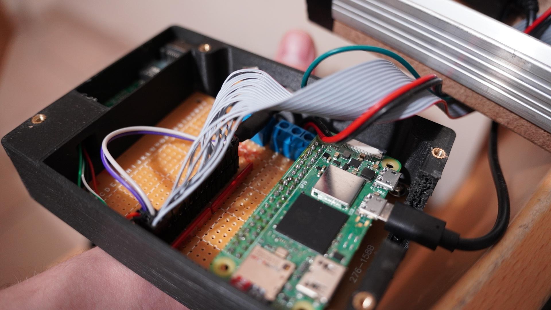
After securing it on the MDF board, it looked perfect.
As I needed it to work as soon as possible 🐇, I went with something I knew for sure and used python 🐍.
The first thing I did was test out the LEDs and inputs. I used the circuit python libraries because it just works. Didn't have to fiddle to make something work correctly. And, sure enough, everything worked right away, nice 👍.
Initially, I did everything in one big script, but that became an issue when I had multiple loops and a web server.
I then thought that it might be better / easier to write a few interconnected modules than to write a big one 🤔. There are a few options for connecting multiple parts together. ZMQ and MQTT are pretty popular, I then remembered that MQTT has a web socket version (which I could easily use for a Web UI later 🌐) and went with it.
I chose to use the mosquito mqtt server, installing it was pretty straightforward:
1sudo apt update
2sudo apt install -y mosquitto mosquitto-clients
3sudo systemctl enable mosquitto.service
Then, I just need to enable anonymous access, traditional MQTT and Websocket support in the config:
1listener 1883
2listener 8080
3protocol websockets
4allow_anonymous true
Note: using authentication here wouldn't be very useful, since the credentials could have been easily recovered in the source code of the webui 🤷♂️
After a quick test with the MQTT explorer app on my computer to check that it was working. So, I went ahead and started working on the global config.
The config.py file of x32_tally contains several variables that I can configure to alter the way the tool works. This includes:
The io.py file contains definitions for the LedController and InputController classes. These act as a wrapper for the Adafruit libraries, this allows me/someone to easily change the input/output method without the need to rewrite every module 😏.
 1class LedController:
 2	def __init__(self):
 3		highest_pixel_id = 0
 4		for ch_n, ch in config.input_channels.items():
 5			if "tally_leds" in ch:
 6				highest_pixel_id = max(highest_pixel_id, *ch["tally_leds"])
 7		self.pixels = neopixel.NeoPixel(config.tally_neopixel_pin, highest_pixel_id + 1, auto_write=False)
 8
 9	def update(self):
10		self.pixels.show()
11
12	def set(self, leds, r, g, b):
13		for led in leds:
14			self.pixels[led] = (r, g, b)
1class InputController:
2	def __init__(self):
3		self.buttons = {}
4
5	def get(self, pin):
6		if pin.id not in self.buttons:
7			self.buttons[pin.id] = digitalio.DigitalInOut(pin)
8			self.buttons[pin.id].direction = digitalio.Direction.INPUT
9		return self.buttons[pin.id].value
This file also contains a function for creating MQTT clients. It takes a name and returns the client:
1def get_mqtt_client(client_id):
2	client = mqtt.Client(
3		client_id=client_id,
4		reconnect_on_failure=True
5	)
6
7	client.enable_logger(logging.getLogger("MQTT"))
8	client.connect(config.mqtt["host"], config.mqtt["port"], 60)
9	return client
Finally, this module also broadcasts the input channel config every time it's loaded. This is only for the Web UI, as it obviously doesn't have access to the config.py file.
As the headline suggests, the most important thing is to forward messages from the M32 to the MQTT server so that other modules can access it.
As a request from the sound engineer, I purposefully did not implement the MQTT to M32 side to avoid something writing to the console and causing something bad 😕 (That being said, it would be trivial to implement).
The MIDAS M32 uses a custom implementation of the OSC protocol. OSC is wonderful, works super well, and it's widely used. It's no wonder they used it.
One tiny annoying thing about their implementation is that you need to send packets to the port 10023 of the console. But it does not respond to you on 10023, instead it responds to whatever ephemeral port the system decided to use to send the packet. This means that you need to keep the same socket.
It's a small inconvenience, but it also means that you don't have to select a different port for each app 👍.
Somebody did an incredible job of reverse engineering what each command does and published a ton of software for the X32. Including an emulator, which is helpful when you don't have the 3600 EUR console next to you. He also published a spec sheet of OSC commands which is very useful.
Turns out that to query a setting of the console you just have to send the same command that you would normally send for setting it but without the parameters.
Essentially, that would mean that I need to send /ch/XX/mix/on and /ch/XX/mix/fader every few hundreds of a second to poll the status. That would be quite resource intensive for both devices 😓.
Instead, the engineers over at Behringer/Midas added the /xremote command, this command will subscribe you to every update happening on the console (except VU meters for which there is a special command). The only thing is that you need to resubscribe every few seconds to keep receiving updates 👍.
To recap, I send:
/xremote command to subscribe to console updates./ch/XX/mix/on query to get the mute status of the channel XX,/ch/XX/mix/fader query to get the fader value of the channel XX,/ch/XX/config/icon query to get the icon of the channel XX,/ch/XX/config/name query to get the name of the channel XX,/ch/XX/config/color query to get the color of the channel XX.Unfortunately, after some testing with the real thing (as I started the development with an emulator), it turns out that the /xremote command doesn't send every fader update when changing cues, and it meant I had to wait for the forced update to refresh the status 😕.
To solve this, I had to dive into how the /formatsubscribe command works. This command allows the reception of regular updates for a topic. In this case, I subscribed to mute and fader values.
Note that this command did not work on the emulator, hence why I didn't use it from the start 🤷♂️.
On a tangent, I also looked at the /showdump, /-prefs/show_control, /‐show/prepos/current and /-show/showfile/show/name commands that allow me to get the show, its cues and the current position of cues.
So, how does that work in code. I used the pythonosc module to parse and build the OSC messages. I then wrote a class that inherit from threading.Thread to keep receiving the messages in the background. This is probably not necessary, but I wanted to be able to re-use this lib somewhere else if needed. I started by creating a few helper functions.
I first wrote a "send" function that wouldn't make the module crash if, for some reason, the network was not working.
 1    # Wrapper function use to send data to the console.
 2    # The function tries to send the message but does not raise an error if it fails (it just logs it).
 3    # This can happen if the network card is not up yet
 4    def _send(self, data: bytes):
 5        try:
 6            self._socket.sendto(data, self._address)
 7        except OSError as e:
 8            self._log.warning(f"Tried to send data but got: {e}")
 9        except Exception as e:
10            self._log.error(f"Tried to send data but got: {e}")
Next, I wrote wrappers around the OSC commands of the x32 that I'll often use.
 1    def _x32_format_subscribe(self, alias, addresses, start_i, end_i, interval=20):
 2        message = OscMessageBuilder("/formatsubscribe")
 3        message.add_arg(alias)
 4        for address in addresses:
 5            message.add_arg(address)
 6        message.add_arg(start_i)
 7        message.add_arg(end_i)
 8        message.add_arg(interval)
 9        self._send(message.build().dgram)
10
11    def _x32_renew(self, alias):
12        message = OscMessageBuilder("/renew")
13        message.add_arg(alias)
14        self._send(message.build().dgram)
15
16    def _x32_xremote(self):
17        message = OscMessageBuilder("/xremote")
18        self._send(message.build().dgram)
19
20    def _x32_info(self):
21        message = OscMessageBuilder("/info")
22        self._send(message.build().dgram)
23
24    def _x32_showdump(self):
25        message = OscMessageBuilder("/showdump")
26        self._send(message.build().dgram)
Followed that with a function to force query the status of the fader and to dump the whole show.
 1    def _query_channel(self, channel):
 2        self._send(OscMessageBuilder(f"/ch/{channel:02}/mix/on").build().dgram)
 3        self._send(OscMessageBuilder(f"/ch/{channel:02}/mix/fader").build().dgram)
 4        self._send(OscMessageBuilder(f"/ch/{channel:02}/config/icon").build().dgram)
 5        self._send(OscMessageBuilder(f"/ch/{channel:02}/config/name").build().dgram)
 6        self._send(OscMessageBuilder(f"/ch/{channel:02}/config/color").build().dgram)
 7
 8    def _query_show(self):
 9        self._x32_showdump()
10        self._send(OscMessageBuilder(f"/-prefs/show_control").build().dgram)
11        self._send(OscMessageBuilder(f"/‐show/prepos/current").build().dgram)
12        self._send(OscMessageBuilder(f"/-show/showfile/show/name").build().dgram)
Next, I did the re-sync and resubscribe functions. These functions are called respectively every 60 sec and every 5 sec.
The goal of the _re_sync is to be damn sure that our information is sync with the console. It also forces a /formatsubscribe command instead of a /renew.
The goal of the _re_subscribe command is to send the /renew, /xremote and /info commands to make sure we keep the update coming.
 1    # Resync function. This function is executed every 60sec to make sure the internal status is up-to-date with the console
 2    def _re_sync(self):
 3        self._log.info("[TX] Forced queried infos and subscribed")
 4        self.last_resync = time.time()
 5
 6        for i in range(1, 33):
 7            self._query_channel(i)
 8
 9        self._x32_format_subscribe(
10            alias="/subscribed/faders",
11            addresses=["/ch/**/mix/on", "/ch/**/mix/fader"],
12            start_i=1, end_i=32,
13            interval=20
14        )
15
16        self._query_show()
17
18    # Resubscribe function. This function is executed every 5sec to subscribe to updates from the console
19    def _re_subscribe(self):
20        self.last_resubscribe = time.time()
21        self._log.info("[TX] Renewed subscriptions")
22        self._x32_xremote()
23        self._x32_info()
24        self._x32_renew("/subscribed/faders")
Now that we can send messages, we need to receive them. I started by writing a handler for all messages. This function receives an OSC message and forward it to the appropriate internal or external handler.
 1    # Internal OSC message handler
 2    def handle_message(self, message):
 3        self.last_incoming = time.time() # Reset the last incoming timer
 4
 5        if message.address == "/subscribed/faders":
 6            self.handle_message__subscribed_faders(message)
 7            return  # Subscribed aliases are internal message no need to forward it
 8
 9        if message.address == "/node":
10            self.handle_message__node(message)
11            return  # Can't forward node responses
12
13        # If the address is "/info" retrieve the server version/name and the console model/version and trigger the connection handlers
14        if message.address == "/info":
15            self.handle_message__info(message)
16
17        # The message to every other handler
18        for handler in self.handlers:
19            handler(message)
The /info handler is basic. It simply extracts the information, stores it and calls every "connection" handler.
1    def handle_message__info(self, message):
2        self.x32_server_version = message.params[0]
3        self.x32_server_name = message.params[1]
4        self.x32_console_model = message.params[2]
5        self.x32_console_version = message.params[3]
6        for handler in self.connection_handlers:
7             handler(self.has_connection)
The handler for /node responses is a bit more complex. The node messages are basically an OSC message converted to a string and terminated by a newline. The only (string) argument looks a bit like this /-prefs/iQ/01 none "Linear" 0\n. To parse it, I used the shlex module to do lexical analysis of the received text (because the quoted text might contain space, I can't use a simple split). Using this method, the address is the first element, then I check if every parameter is a float or an int, if not, it defaults to a string. Then, I call the handle_message recursively to redistribute the message.
1    def handle_message__node(self, message):
2        data = shlex.split(message.params[0][:-1])
3        msg = OscMessageBuilder(data[0])
4        for param in data[1:]:
5            msg.add_arg((int(float(param)) if float(param).is_integer() else float(param)) if _is_number_tryexcept(param) else param)
6        self.handle_message(msg.build())
The /formatsubscribe command will send one binary blob message instead of multiple messages for everything subscribed. Since I subscribe to /ch/**/mix/on and /ch/**/mix/fader with a start of 1 and an end of 32 the console sends a binary blob consisting of 32 int32 for the mute status and 32 float32 for the fader values. Decoding this is straightforward thanks to the struct module and this format <i32i32f. Then I again call the handle_message recursively with "fake" messages
 1    def handle_message__subscribed_faders(self, message):
 2        if len(message.params[0]) != (4 + 4 * 32 + 4 * 32):
 3            self._log.warning("Messaged recevied by the /subscribed/faders handler that doesn't have the right size ({len(message.params[0])} != 260)")
 4            return
 5        data = struct.unpack(f"<i32i32f", message.params[0])[1:]  # Ignore first byte which is the length
 6        # Fake messages to maintain compatibility
 7        for i, value in enumerate(data[:32]):
 8            msg = OscMessageBuilder(f"/ch/{i+1:02}/mix/on")
 9            msg.add_arg(value)
10            self.handle_message(msg.build())
11        for i, value in enumerate(data[32:]):
12            msg = OscMessageBuilder(f"/ch/{i+1:02}/mix/fader")
13            msg.add_arg(value)
14            self.handle_message(msg.build())
This loop is responsible for:
_re_sync function every 60sec1 if self.last_resync + 60 < time.time():
2 self._re_sync()
_re_subscribe function every 5sec1 if self.last_resubscribe + 5 < time.time():
2 self._re_subscribe()
1            # Connection status check
2            if last_connection_status != self.has_connection:
3                last_connection_status = self.has_connection
4                # Notify handlers
5                for handler in self.connection_handlers:
6                    handler(self.has_connection)
7                # Force a resync if we just connected
8                if self.has_connection:
9                    self._re_sync()
 1            try:
 2                # A while loop here will ensure that if there is still data incoming it will be read before processing re-syncs
 3                # recvfrom will throw an error if there isn't anything thus exiting the loop
 4                while True:
 5                    # Receive data from the socket
 6                    data, peer = self._socket.recvfrom(1024)
 7
 8                    # If data is present, and it's an OSC message, send it to the internal handler
 9                    if data and OscMessage.dgram_is_message(data):
10                        self.handle_message(OscMessage(data))
11                    # The message might also be a "/node" message from the console. These message don't start with / and thus don't comply with the OCS standard.
12                    # Manually correct the address and send it to the internal handler
13                    elif data.startswith(b"node"):
14                        data = data.replace(b"node\x00\x00\x00\x00", b"/node\x00\x00\x00")
15                        self.handle_message(OscMessage(data))
16                    # If data is present, and it's an OSC bundle, unpack it and send all message to the internal handler
17                    elif data and OscBundle.dgram_is_bundle(data):
18                        for message in OscBundle(data):
19                            self.handle_message(message)
20                    else:
21                        self._log.error(f"Received invalid data: {data}")
22            except BlockingIOError:
23                # Ignore BlockingIO errors
24                pass
Quick note on the /node message: Unfortunately, Midas/Behringer didn't fully follow the OSC spec and the node messages don't start with the / 😕, they are padded properly though, so all it takes is a simple .replace before handling the message 🎉.
In the __main__ of the module, I simply start an MQTT client and the M32 client and forward every incoming message OSC to MQTT with the topic prefixed by modules/osc:
 1def forward_to_mqtt(message: OscMessage):
 2    client.publish(
 3        topic=f"modules/osc{message.address}",
 4        payload=json.dumps(message.params),
 5        retain=True
 6    )
 7
 8
 9# Define the function that sends out the status of the module
10def publish_connection_status(is_connected):
11    client.publish(
12        topic=f"modules/osc/status",
13        payload=json.dumps({
14            "connected": is_connected,
15            "x32_server_version": x32.x32_server_version,
16            "x32_server_name": x32.x32_server_name,
17            "x32_console_model": x32.x32_console_model,
18            "x32_console_version": x32.x32_console_version,
19        }),
20        retain=True
21    )
22
23
24x32 = X32(x32_address)
25x32.handlers.append(forward_to_mqtt)
26x32.connection_handlers.append(publish_connection_status)
27x32.start()
Note that the message is published with the retain=True this means that the server will keep a copy of the last message and will send the last value every time a client subscribes to the topic
That module is dead simple, t's only job is simple to send out any updates to the MQTT server:
 1while True:
 2    for ch, input_channel in config.input_channels.items():
 3        # Get (if possible) the value of the buttons, Defaults to None if the channel does not have a button
 4        channel_value = None
 5        if "on_stand_button" in input_channel:
 6            channel_value = inputs.get(input_channel["on_stand_button"])
 7
 8        # If the status has changed, publish the values over MQTT
 9        if ch not in last_channel_values or last_channel_values[ch] != channel_value:
10            last_channel_values[ch] = channel_value
11            client.publish(
12                topic=f"modules/stand_buttons/{ch:02d}/status",
13                payload=json.dumps({
14                    "enabled": input_channel["enabled"],
15                    "has_button": "on_stand_button" in input_channel,
16                    "value": channel_value,
17                    "last_update": time.time()
18                }),
19                retain=True
20            )
21            client.publish(f"ONSTAND_DETECTION/ch/{ch:02d}/is_on_stand", last_status[ch], retain=True)
It loops through all channels that have input configured and check if the microphone is in the holder. Only if the current value is different from the old value, it sends an update to the modules/stand_buttons/XX/status with a JSON dict containing:
Same as before, the message is published with the retain=True which means that the server will keep a copy of the last message.
This module is basic but a bit more involved as it needs to keep a history of the messages received. In simple terms, every time a message is received, it's put in a dict with the key being the topic.
 1message_history = {}
 2
 3def on_message(client, userdata, msg):
 4	global message_history
 5	try:
 6		message_history[msg.topic] = json.loads(msg.payload)
 7	except json.decoder.JSONDecodeError as e:
 8		pass
 9
10client.on_message  =  on_message
11
12def try_get(obj, topic):
13	if topic in obj:
14		return obj[topic]
15	return None
To avoid iterating over a channel that doesn't have LEDs, I added a filter that creates a dict with only channels that have LEDs:
1input_channels_with_leds = {
2	ch: input_channel
3	for ch, input_channel in config.input_channels.items()
4	if "tally_leds" in input_channel
5}
Then there are two functions. One will do an animation with the LEDs and is used when the OSC module reports that it cannot connect to the M32. This animation is a simple ping-pong style animation with LEDs.
The more interesting function is the do_tally_lights function. This one is responsible for looping over every channel with an LED:
1def do_tally_lights():
2    # Loop over every channel that have LEDs
3    for ch, input_channel in input_channels_with_leds.items():
4        # Set the default color to black
5        color = [0, 0, 0]
Getting the vales from the history
1        # Get the mute, fader and is_on_stand values from the history
2        x32_on = try_get(message_history, f"modules/osc/ch/{ch:02d}/mix/on")
3        x32_fader = try_get(message_history, f"modules/osc/ch/{ch:02d}/mix/fader")
4        module_is_on_stand = try_get(message_history, f"modules/stand_buttons/{ch:02d}/status")
Checking that the channel is actually enabled
1        # If the channel is enabled
2        if input_channel["enabled"]:
3            # If the value stored in the history for the mute and fader values are not None
Checking that there is, a history for either the fader or the mute status, If there isn't that either means that the channel doesn't exist or wasn't updated yet. I then set the LEDs to black in this case.
On the other hand, if I have a value I then determine if the channel is active, meaning unmuted and a fader being at more than 8%. If it's active, I turn the LEDs green and set the LEDs to red if inactive.
1            if x32_on is not None and x32_fader is not None:
2                # Calculate if the channel is active
3                is_active = x32_on[0] and x32_fader[0] > 0.08
4
5                # Set the channel color
6                color = config.tally_colors["active"] if is_active else config.tally_colors["muted"]
Then, it checks if there is a history for the "is on stand" value. If the microphone is on the holder but is active or if the microphone is not on the holder and inactive, I blink the LEDs brightness to signal an issue.
 1                # if the value stored in the history for the is_on_stand is not None
 2                if module_is_on_stand is not None:
 3                    # If the channel is active and in the stand or not active and not in the stand
 4                    if module_is_on_stand["value"] == is_active:
 5                        # Math tricks to make it blink slower
 6                        if int(time.time() * 5) % 2 == 0:
 7                            # Set the bright color to the channel
 8                            color = config.tally_colors["active_in_stand_on"] if is_active else config.tally_colors["muted_not_in_stand_on"]
 9                        else:
10                            color = config.tally_colors["active_in_stand_off"] if is_active else config.tally_colors["muted_not_in_stand_off"]
Then to finish, I set the color and set the LEDs:
1 leds.set(leds=input_channel["tally_leds"], r=color[0], g=color[1], b=color[2])
Then in the main loop, I check the status of the OSC module, choose the correct animation and update the LEDs
 1while True:
 2    # Get the OSC module status
 3    osc_status = try_get(message_history, f"modules/osc/status")
 4
 5    # Test if the OSC module is connected and execute the proper function
 6    if osc_status is None or not osc_status["connected"]:
 7        do_disconnected_animation()
 8    else:
 9        do_tally_lights()
10
11    # Update the leds
12    leds.update()
13    time.sleep(0.05)
I might do a third color if the channel is unmuted, but the fader is down. This would signal that the sound engineer is ready for the next part, and is about to enable them.
One thing that would be very useful is the ability to see the status of the microphones in the mixing booth. To accomplish that, I wrote a basic app based on Vue.js that uses MQTT thanks to Websockets and the mqttjs library.
The web app subscribes to the data of all 32 channels (meaning name, icon, mute status and fader value) from MQTT and displays it nicely. The On stand detection is also synced from MQTT if available and will stay gray otherwise.
As a sidenote, getting these stupid icons was not fun, while they are in the spec sheet of the unofficial M32 OSC doc, it's one big image not 70+ individual images. I had to dig out some old OpenCV code to detect the 64×64 black squares and extract them manually. Then, thanks to ImageMagick, I applied a black to alpha filter to get rid of the background. The individual images can be found in the GitHub repo.
Thanks to Vuetify, I didn't need to do a lot of CSS, just for the strips themselves. Once this UI placement was finished, I had a very nice read-only UI that even works on phone (kind of, you need to scroll a lot since I chose to force the cue list open on every device):
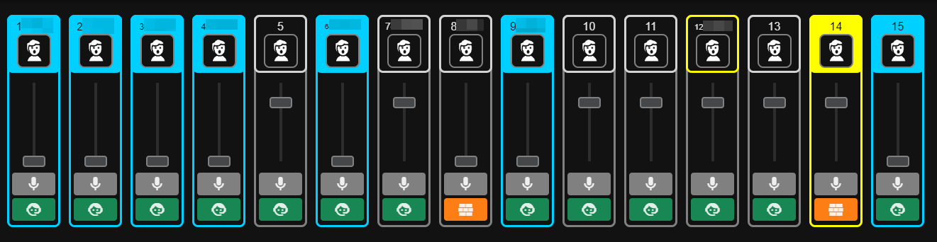
A strip surrounded in blue means that someone has the microphone in his/her hand, but it's still muted. Meanwhile, a yellow border means that it's unmuted on the stand. If a strip doesn't match any of these conditions, the strip reflects the color stored in the X32.
I then built the project to get only static files and started the configuration of the web server. I went with Caddy because it works, it's simple, and the docs are pleasant, and I'm familiar with it.
After following the Debian install instruction from https://caddyserver.com/docs/install#debian-ubuntu-raspbian, I edited the config file as /etc/caddy/Caddyfile it now looks like this:
1:80 {
2	root * /opt/x32_tally/x32_tally/spa_webui/dist/
3	reverse_proxy /mqtt 127.0.0.1:8080
4}
By default, it uses the files located in /opt/x32_tally/x32_tally/spa_webui/dist/ (where the built files are) and also proxies /mqtt to the mosquito Websocket server
All services are pretty similar, for example, the OSC module looks like this:
 1[Unit]
 2Description=X32Tally OSC module
 3After=syslog.target network.target mosquitto.service
 4
 5[Service]
 6Type=simple
 7
 8User=root
 9
10WorkingDirectory=/opt/x32_tally
11ExecStart=python -m x32_tally.osc
12
13Restart=on-failure
14
15[Install]
16WantedBy=default.target
I'm aware that running scripts as root is not the best idea ever. However, I wanted to avoid fiddling with making GPIOs accessible to non-root users, it was just easier this way.
It's something that I would definitively improve have I had more time.
As I mentioned before, the system needs to withstand power cuts. The poor SD card isn't the best thing for the job in the first place, so I choose to make the system read-only. I followed this nicely written guide at https://medium.com/@andreas.schallwig/how-to-make-your-raspberry-pi-file-system-read-only-raspbian-stretch-80c0f7be7353
Now that I had finished, I spent some time doing a diagram that shows how everything interconnects
.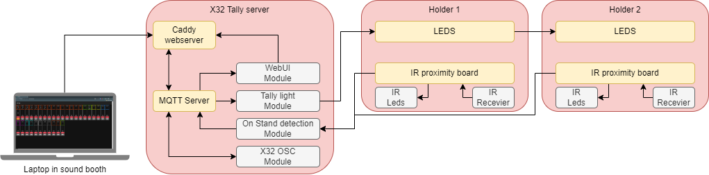
Last week was the first time this system was actually used in production:
And it worked perfectly.
Or that's what I would have said were it not for that stupid network card I used 🤬. That thing worked for 1h and decided to completely stop working right when everyone started to come in.
I don't know the issue for sure, but someone mentioned that it might be due to a potential difference between the power I used, and the one used for everything else. It shouldn't really happen because Ethernet is supposed to be isolated, I guess it wasn't 🤔.
I had to carve out a hole in the controller box to be able to plug a micro USB OTG adapter and plugging a better network card in. I'll re-print everything with a different slot for another network card. Hopefully, that won't happen again.
Apart from that, everything was perfect. Some responses I got range from good to super awesome. 🥳😃
It allowed everyone in the mixing booth to see if we kept a mic open or if forgot to open someone. Backstage, it allowed techs to more easily visualize which microphone was taken at a glance. It also alerted them immediately if there were discrepancies from the mic-sheet.
This system is wonderful, it facilitates the job of the backstage techs and gives more info in the mixing booth. I bet there are quite a few places where this could be very useful.
I think it would even be possible to implement some kind of auto-mixer where it would unmute automatically channels when the microphone is in someone's hand.
I do think that the biggest improvement I could make is using a custom PCB for the holders and printing it in a different material.
Overall, very pleased with this project 😄.
Want to chat about this article? Just post a message down here. Chat is powered by giscus and all discussions can be found here: TheStaticTurtle/blog-comments