Building a stable and secure garage door controller that interfaces to the original controller
This project started a long time ago, the idea is to be able to control the two garage doors remotly.
The garage door that we have is a BFT TIR 60-120 fortunatly the manual (https://www.bft.cz/privat/navody/poh_sekcni/en/TIR 60-120.pdf) includes a cut-down schematic of controller board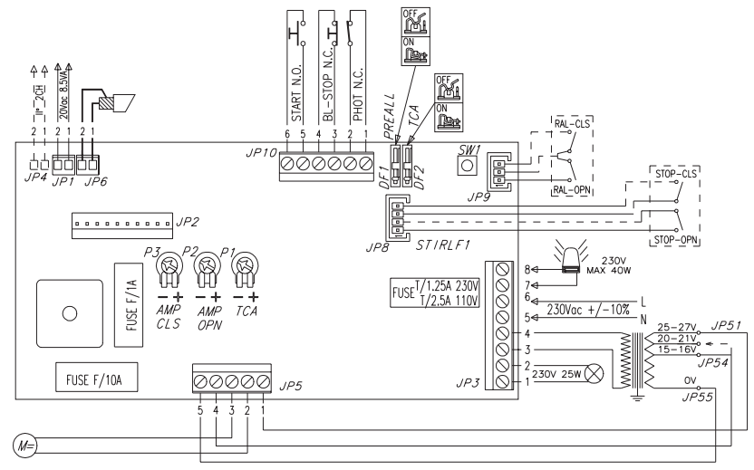
One problem common to all version is that the original button and the rf remote need to be kept functional "just in case"
The 1st version that I made was a simple Arduino with an ENC28J60 and a relay board. You could open the door by sending a UDP packet to the Arduino, and it would power the corresponding relay bridging the door button, after a while I added an authentication message that needed to be sent before sending a command.
The 1st version had a major flaw, it's freaking hard to send a UDP packet from an iPhone with a nice interface without a developer license and all. So the second version used a web interface works great except that it broke every 24h so I kind of dropped it.
The 3rd version has been designed and built to be much more stable/secure.
So, I had multiple options, using a state machine that updates by listening at the button isn't a very good solution because a desynchronization could happen and f-up the whole controller. Instead, I wanted feedback on where the door is (or will be) so it was time to reverse engineer the original controller board.
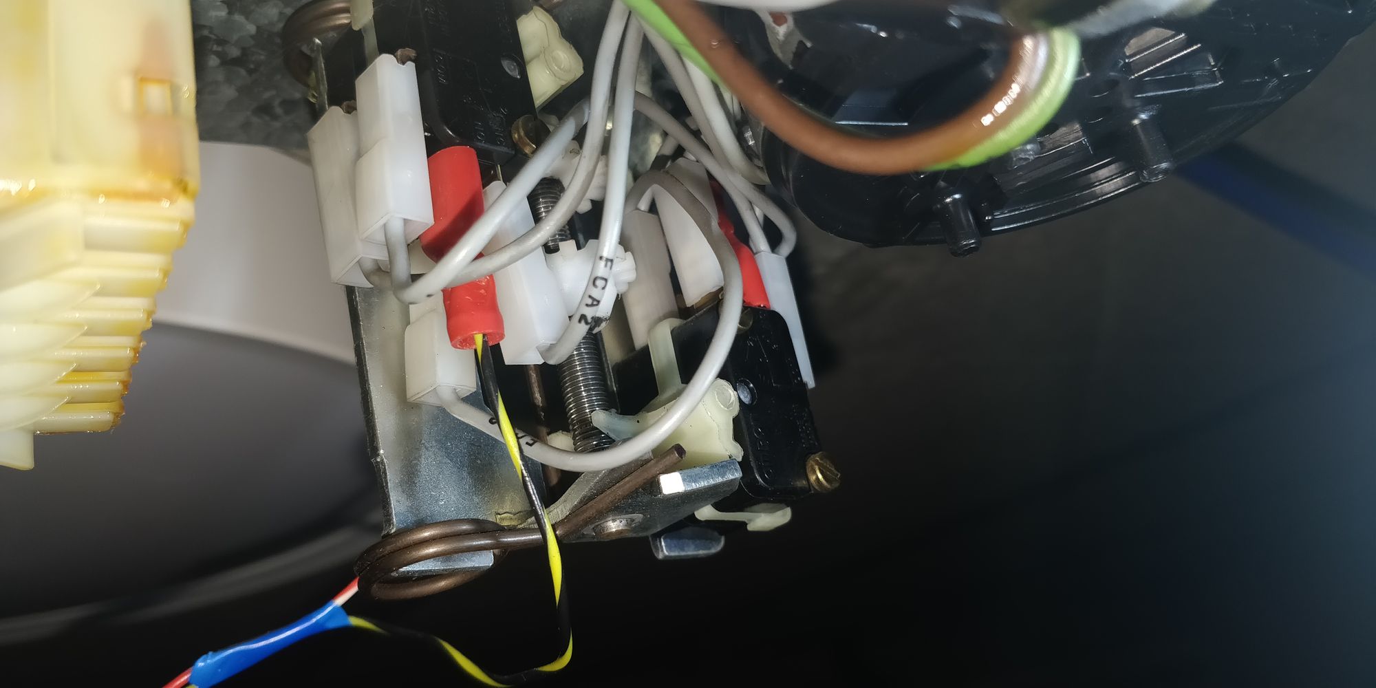
After a bit of thinking using the STOP-CLS and STOP-OPN switches NC signals (which were unpopulated) are perfect to find out if the door is open or closed. However, if the door is stopped in the middle and if we send an order to either open or close the door I also need to know on which direction to door is going in order to stop it and repress the button to let the door go in the other direction.
In order to do that, my best option was to use two DC optocouplers on the motor terminals in order to determinate the direction of rotation of the motor.
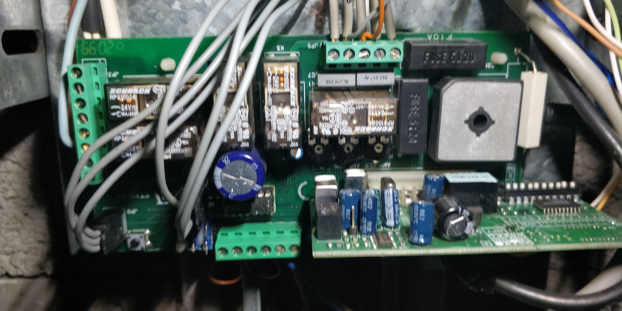
At first, I wanted to avoid soldering myself to the board and only use the available terminal blocks. However, an issue with that is that there was no DC positive to power the optocouplers that was available.
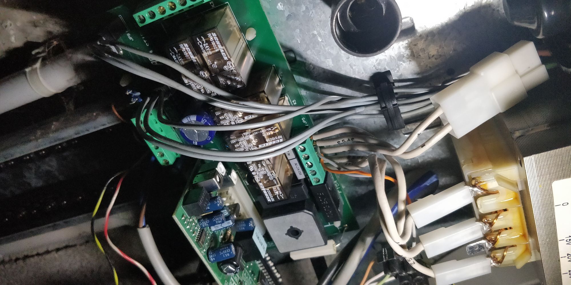
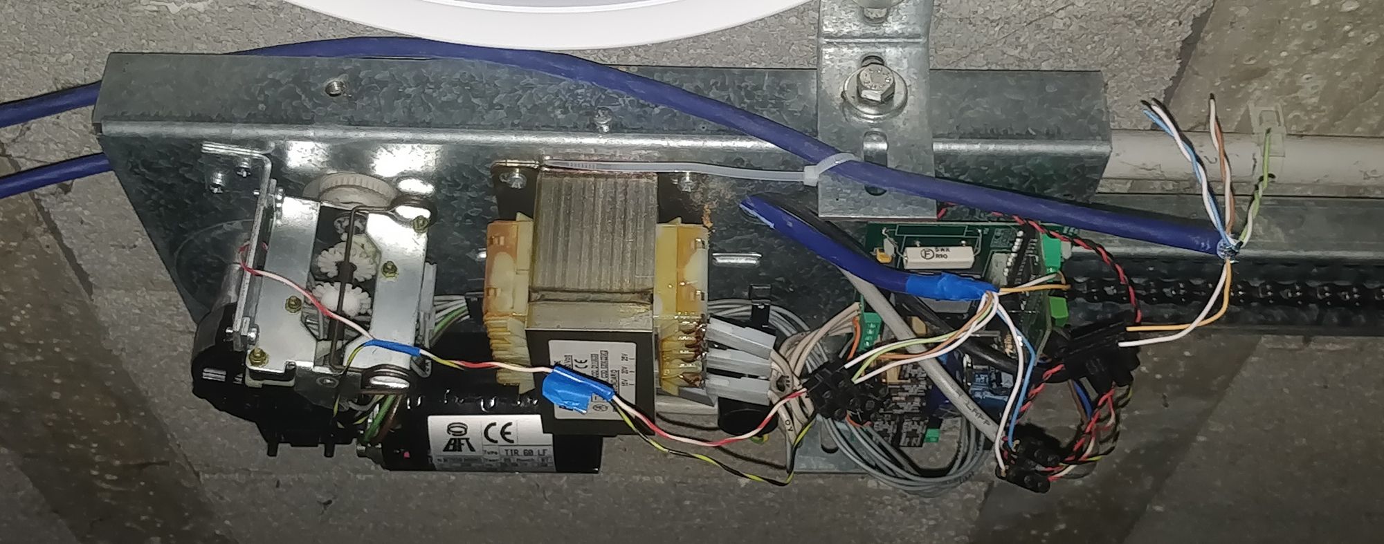
So after much time taking photos of the main board:
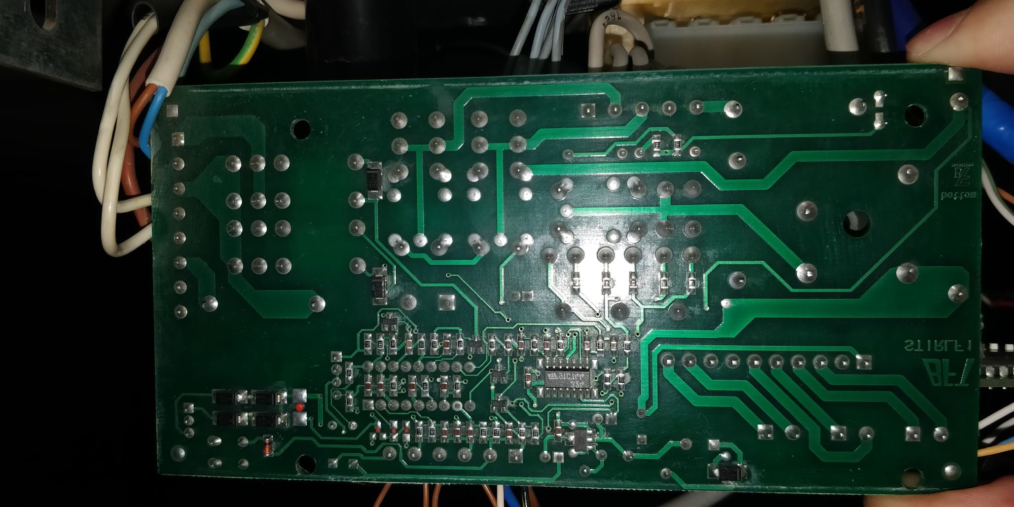

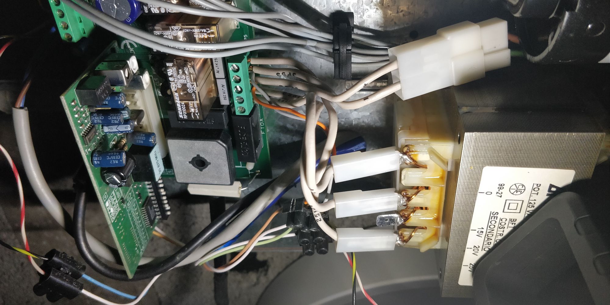
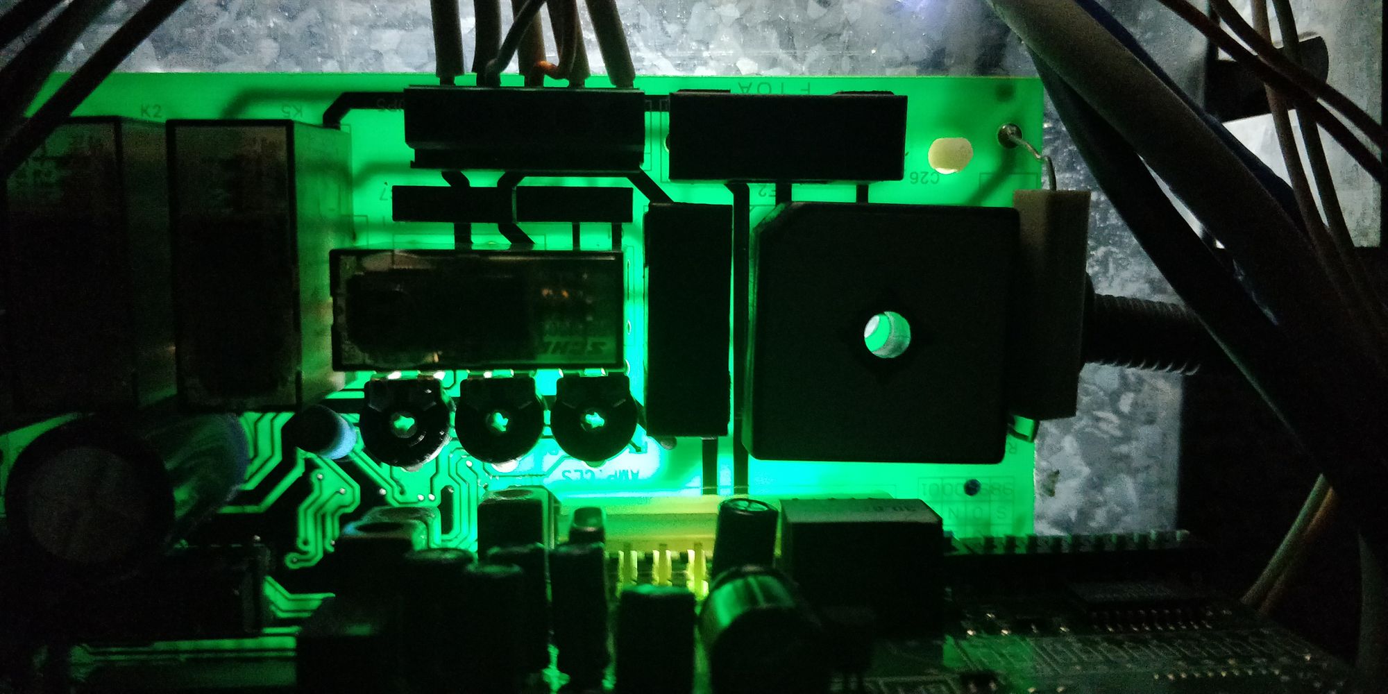
After many hours I produced a schematic with all the power parts of the circuit: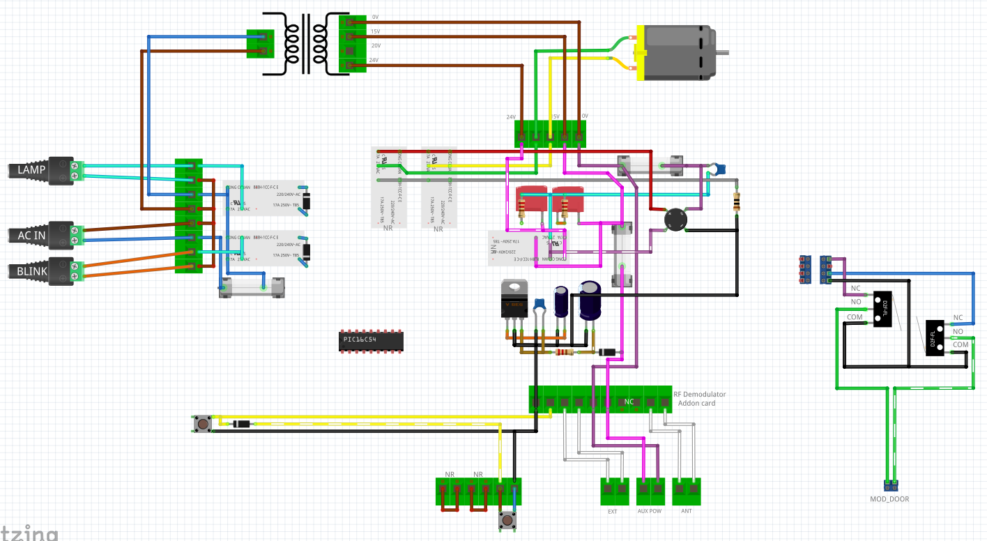
I then decided that the only thing to do is to solder myself to the bridge rectifier that ways I get a ground and a positive.
The next step was to make a schematic for the board that will interface with the existing control board. One challenge that I add to myself was that I didn't want to buy more components for this project
PS: At the time of making the schematic, I wasn't sure what component I'll use, so there are some unnecessary part in order to add more compatibility
Powering the board will be done via the 20V AC out of the controller board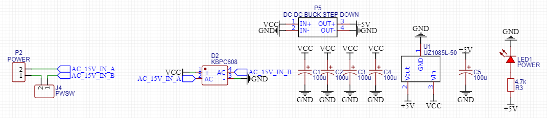
As I said, the motor rotation direction is used via two optocouplers: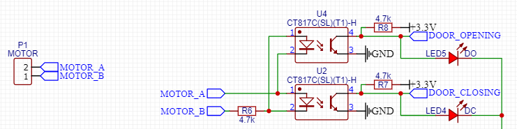
This one is a bit tricker, I could have done some tricks and used a level shifter, but I went on the simpler route and used two more optocouplers.
As I said I soldered a wire on the output terminals of the bridge rectifier and used a zener diode to make the output a known voltage (The motor which is powered by the rectifier has two speeds, see the board schematic)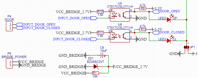
The last connection is the door button for which I used a relay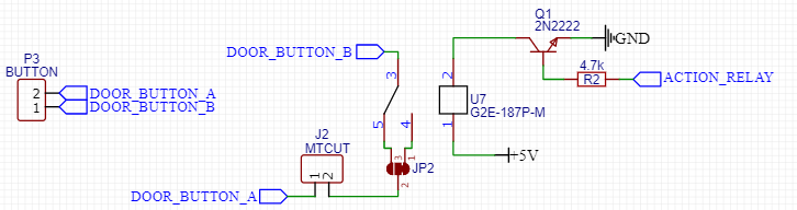
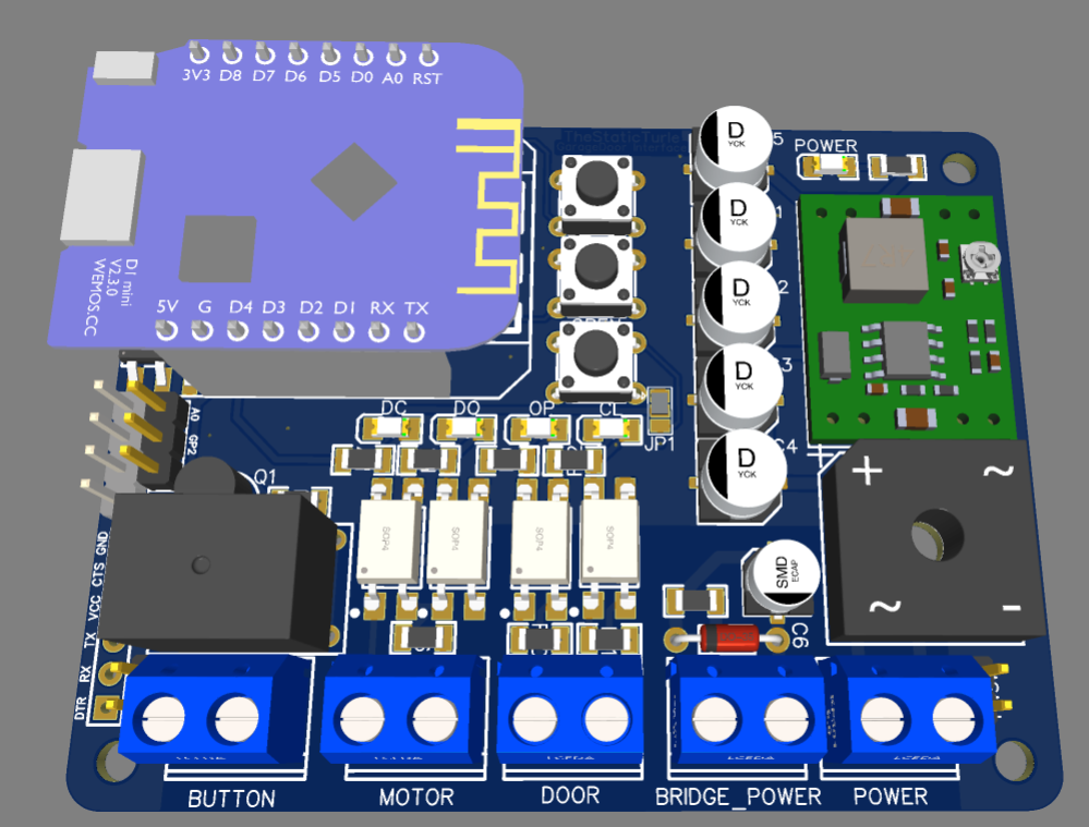
For the mcu I choose a simple esp8266 the only issue is that I didn't know if I wanted to use a d1 mini of directly solder an esp12 to the board. So I added circuitry for both on the schematic: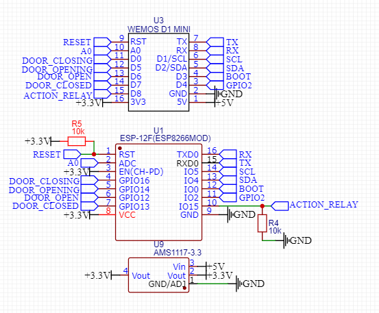
The design was quite simple. You will see on the bottom left of the pcb there are connectors, one is for an FTDI, one is the I2C bus and the last one is two spare gpio (gpio2 and the adc) these ports are for future expansion or some sensors
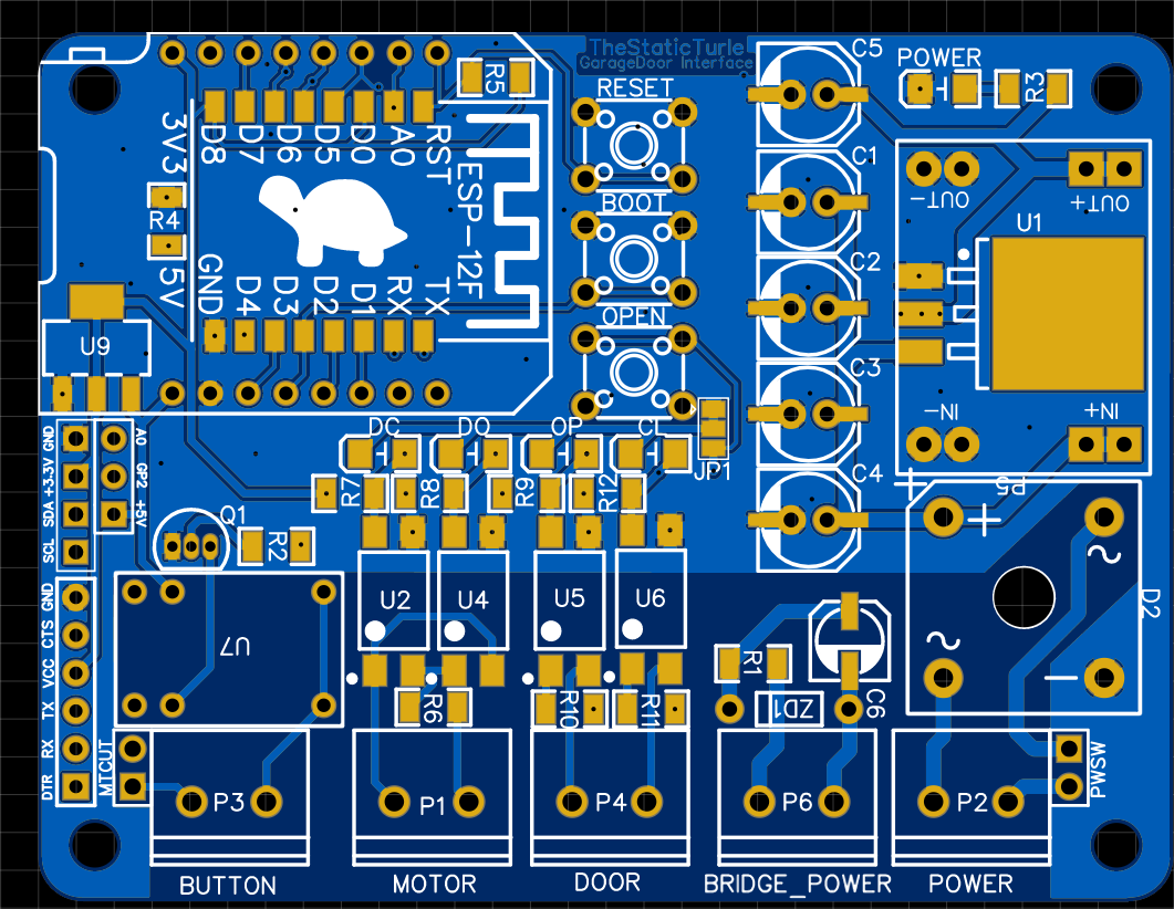
Thankfully, PCBWay stepped in and offered to manufacture the PCB
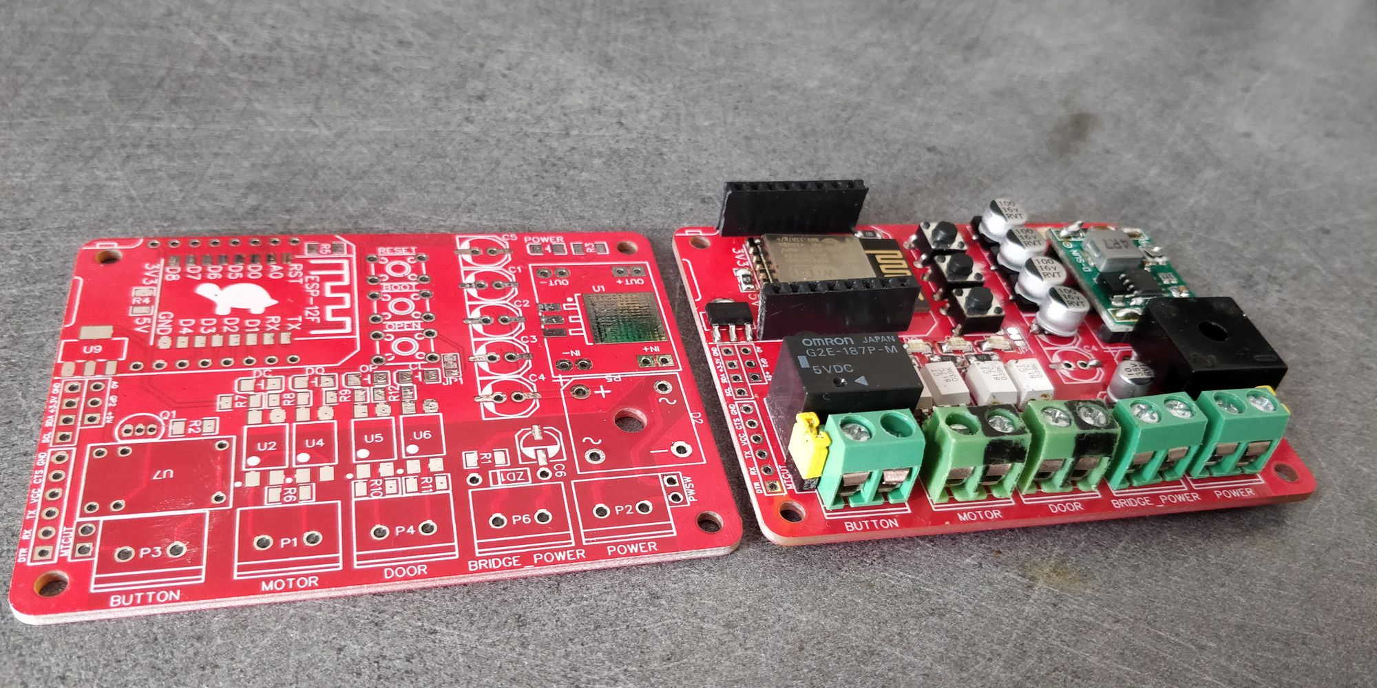
After waiting one week for the pcb to be made
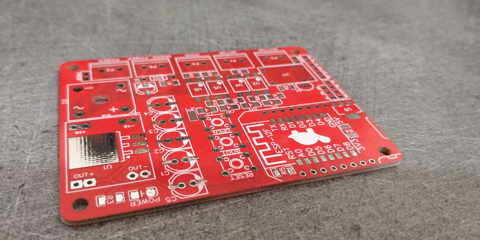
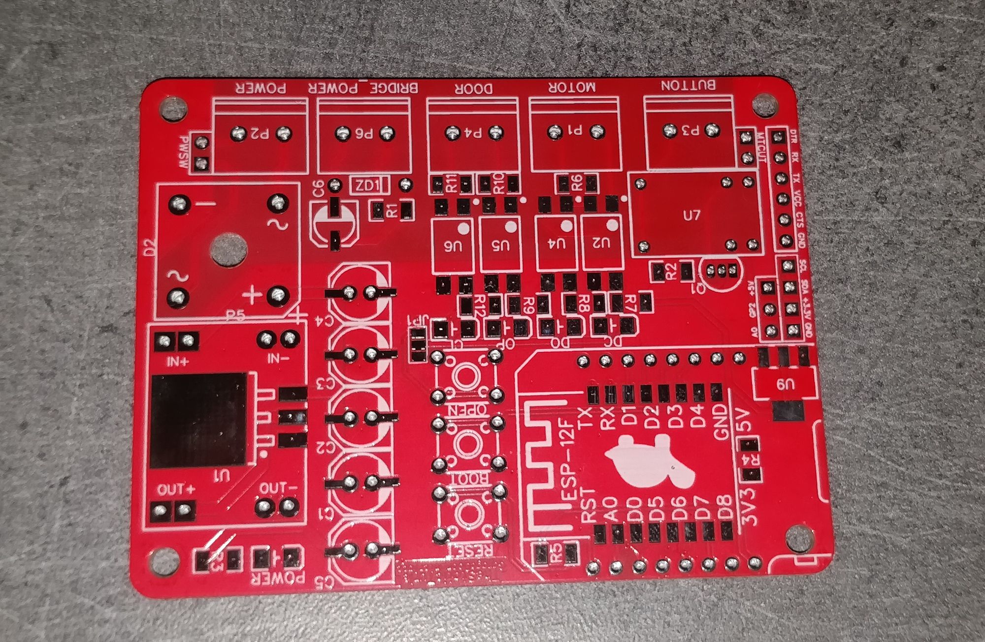
After a bit of inspection, I couldn't find anything wrong with all the 5 boards and the pcb quality is quite good, on one hand the red might not be as vibrant as jlcpcb (but that's looking for something it's not really important) on the other hand the silk screen and the copper traces are fantastic.
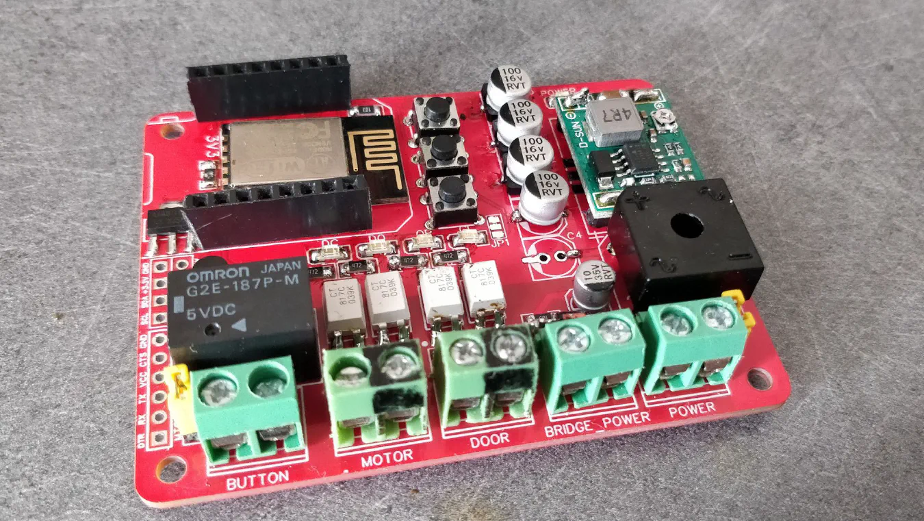
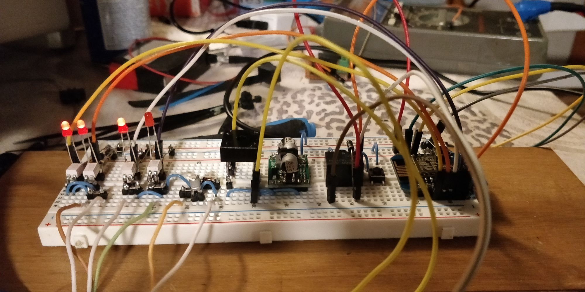
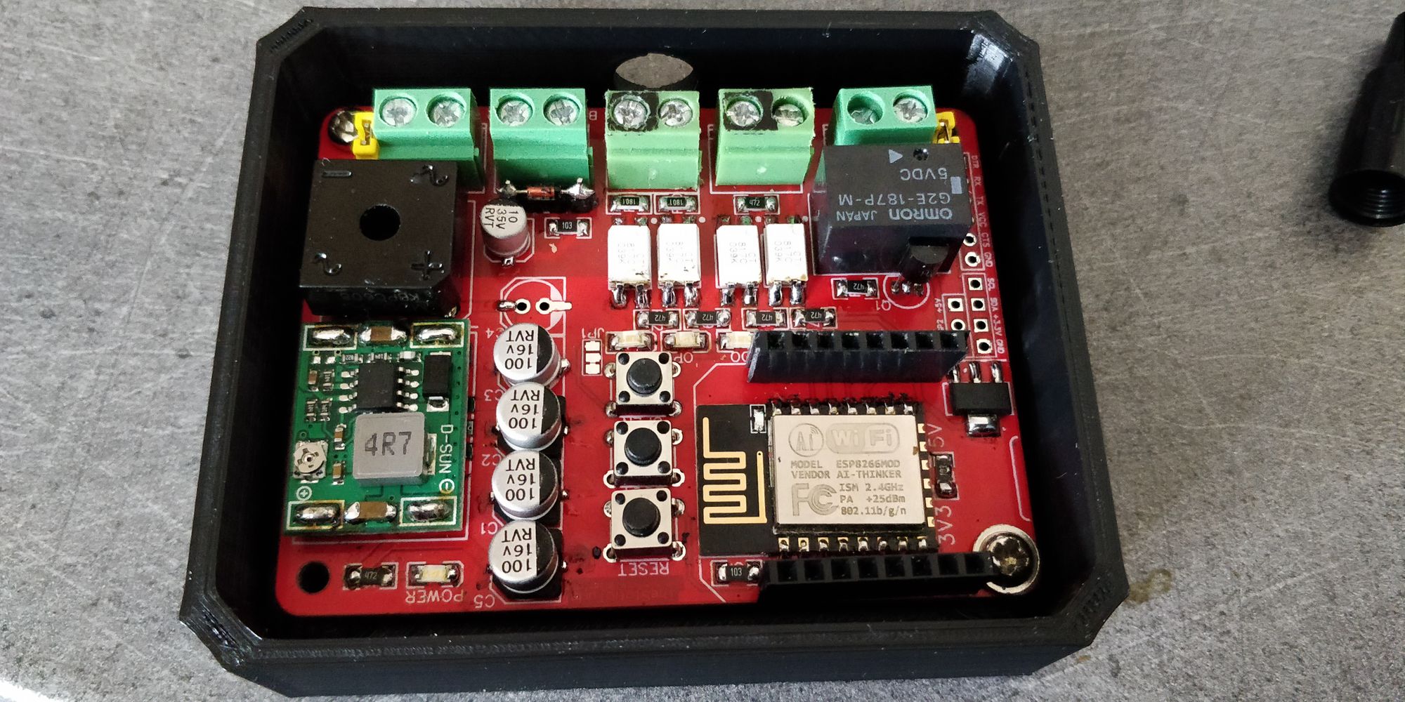
Overall I'm very pleased with pcbway PCBs and after a quick soldering job, I got a wonderful looking board: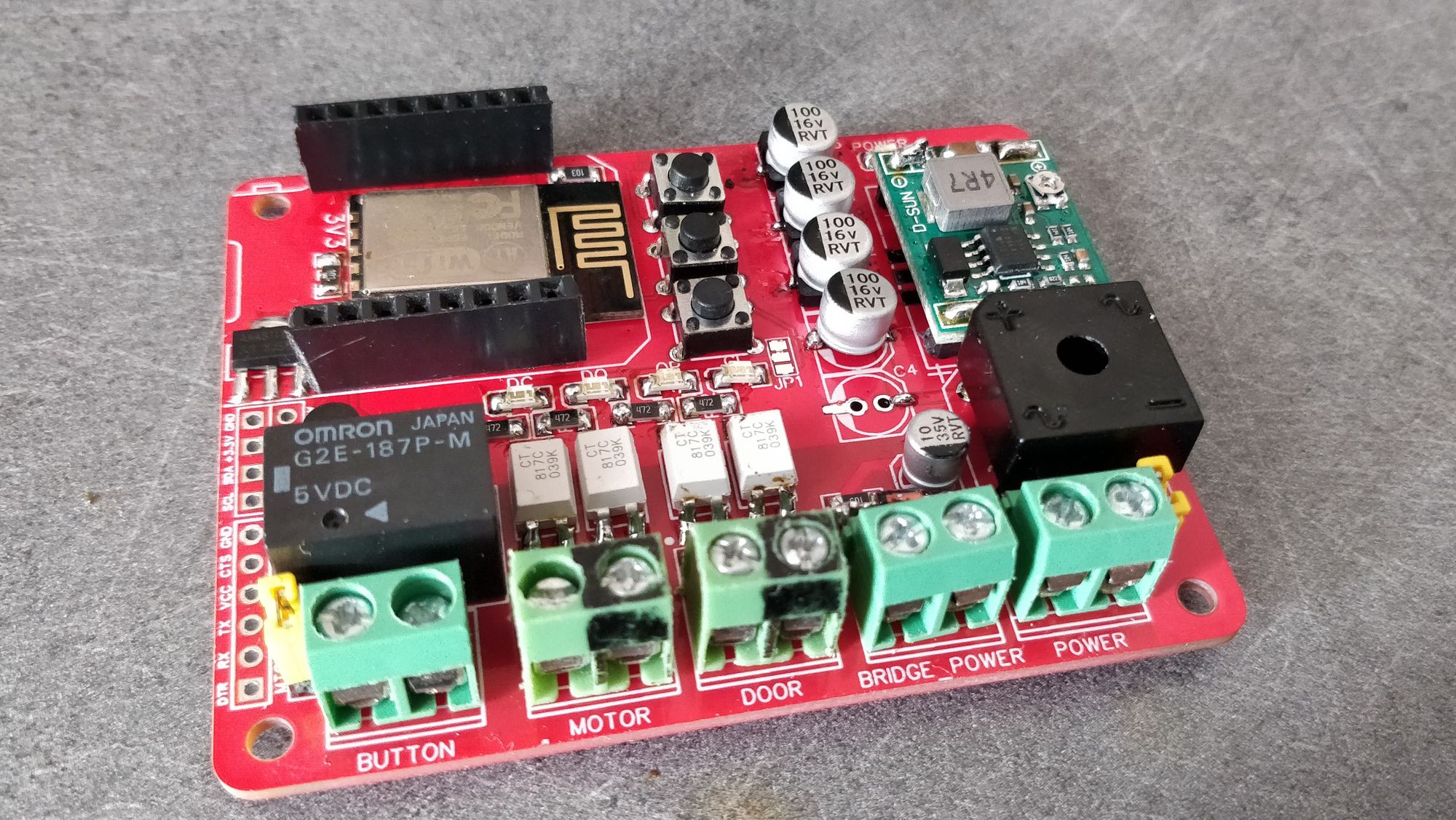
After a quick test, I needed to swap the relay contact and swap a pin in software. After that, the board worked just fine and responded to all my commands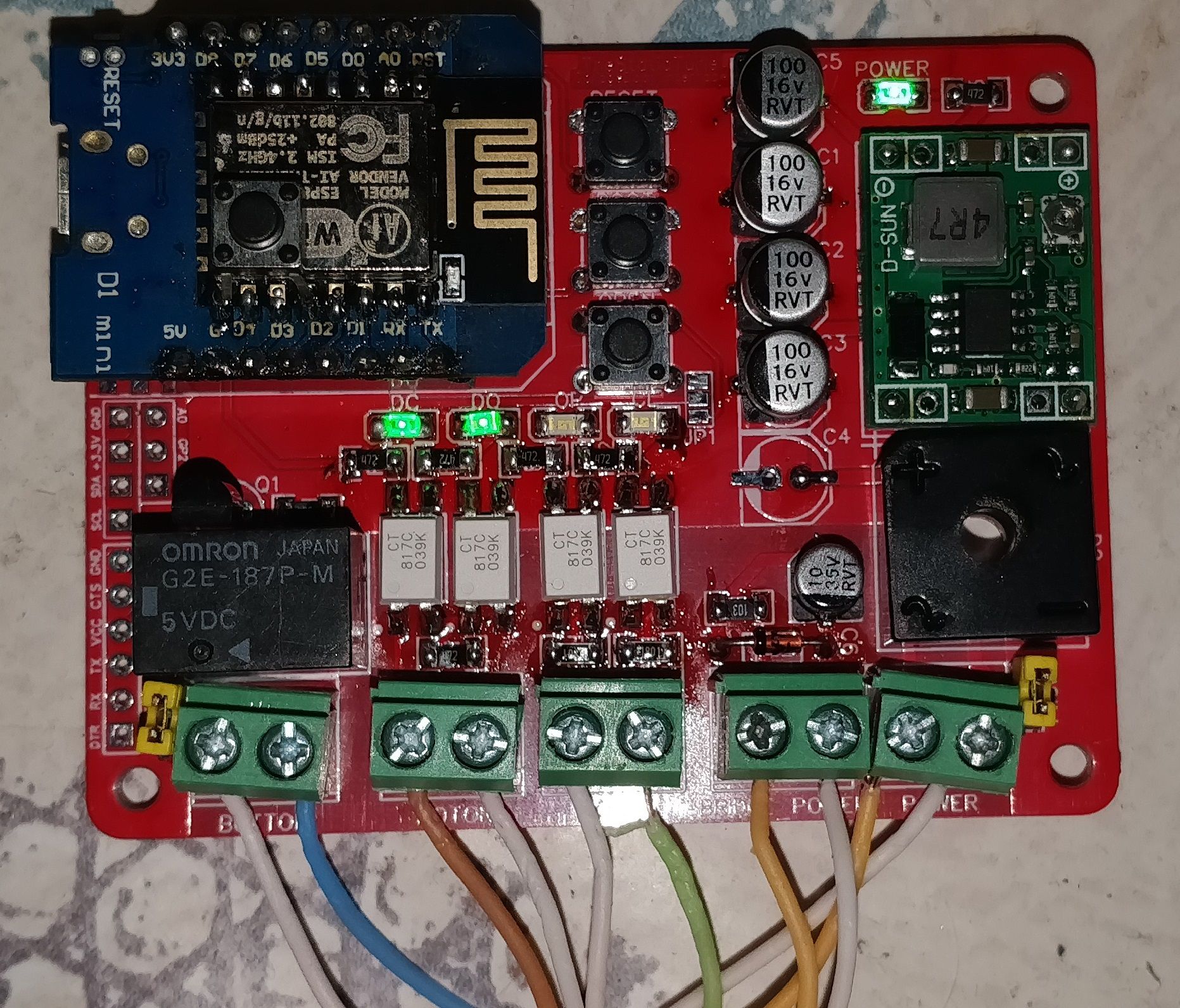
All the software development has been done under the Arduino IDE (to simplfy some stuff) instead of using platformIO
The esp8266 connects to my home Wi-Fi network and then connect to the MQTT server running on my home automation PC.
The node reports the door status and it's status over the serial port, mqtt and to my syslog server.
All the functions use two structs, one for reading the state of the door and an other one for sending commands:
enum door_status_t {
  DS_OPEN           = 0,
  DS_OPEN_PARTIAL   = 1,
  DS_OPENING        = 2,
  DS_CLOSING        = 3,
  DS_CLOSED         = 4,
  DS_ERROR_OPENING_AND_CLOSING   = 248,
  DS_ERROR_CLOSING_WHILE_OPENING = 249,
  DS_ERROR_OPEN_AND_CLOSED       = 250,
  DS_ERROR_OPENING_WHILE_CLOSED  = 251,
  DS_ERROR_UNKNOWN               = 252,
  DS_ERROR_ALL_ON                = 253,
  DS_UNKNOWN = 255,
};
enum move_direction_t {
  MV_STOP   = 0,
  MV_OPEN   = 1,
  MV_CLOSE  = 2,
  //Specials use case
  MV_ANY    = 3,
  MV_CHANGE = 4,
};
The main function responsible to move the door is this one:
bool move_door(move_direction_t direction, int _recur) {
  door_status_t status = getDoorStatus();
  if(direction == MV_OPEN  && (status == DS_OPEN || status == DS_OPENING)) return true;
  if(direction == MV_CLOSE && (status == DS_CLOSED || status == DS_CLOSING)) return true;
  if(direction == MV_STOP  && !(status == DS_OPENING || status == DS_CLOSING)) return true;

  if(_recur >= 5) {
    syslog.log(LOG_WARNING, "move_door maximum recusivity was hit");
    send_pin_status_all(); send_status_update_all(getDoorStatus());
    return false;
  }

  press_action();

  if(wait_for_motor_dir(MV_CHANGE, 2000)) {
    syslog.log(LOG_ERR, "wait_for_motor_dir MV_ANY timeout.");
    send_pin_status_all(); send_status_update_all(getDoorStatus());
    return false;
  }
  delay(50);
  send_status_update_all(getDoorStatus());
  return move_door(direction, _recur+1);
}
First we get the status of the door, then we check if it's the state we want the door to be in, if it's the case, exit the function right away.
Otherwise, press the button (activate the relay), wait for the motor to change the state it is right now send a status update and re-execute the function, this goes on until either the door is going to be in the position we want her to be or either it is on the position we want her to be (or the maximum resistivity security limit was hit).
It is possible tho that the door won't respond to the relay, if it is the case stop the function and report to syslog the error.
The wait function is this one:
bool wait_for_motor_dir(move_direction_t direction, int timeout) {
  unsigned long start_time = millis();
  bool isOpening = !digitalRead(pin_motor_opening);
  bool isClosing = !digitalRead(pin_motor_closing);
  bool isOpening_original = isOpening;
  bool isClosing_original = isClosing;

  while((start_time+timeout) > millis()) {
    isOpening = !digitalRead(pin_motor_opening);
    isClosing = !digitalRead(pin_motor_closing);
    if(direction==MV_OPEN  && isOpening) return true;
    if(direction==MV_CLOSE && isClosing) return true;
    if(direction==MV_ANY   && (isClosing || isOpening)) return true;
    if(direction==MV_STOP  && !isOpening && !isClosing) return true;
    if(direction==MV_CHANGE  && (isOpening != isOpening_original || isClosing != isClosing_original)) return true;
    ESP.wdtFeed();
  }

  delay(75);
  return false;
}
First, we read the status of the motor (for the MV_CHANGE), next, we enter a loop where we get the status of the motor, and check if it is the status we want if yes return true. If the timeout is hit just return false.
This function shouldn't run long to cause any problem with the OTA library or anything else. However, should an error occur somewhere the ESP.wdtFeed(); is there to prevent the ESP from rebooting and not sending an error message
Here I ran into a bit of a problem, you see here are the message transmitted via mqtt: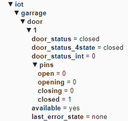
Here is the homeassitant configuration:
cover:
  - platform: mqtt
    device_class: garage
    name: "Porte garage david"
    availability_topic: "iot/garrage/door/1/available"
    payload_available: "yes"
    payload_not_available: "no"
    command_topic: "iot/garrage/door/1/command"
    payload_open: "open"
    payload_close: "close"
    payload_stop: "stop"
    state_topic: "iot/garrage/door/1/door_status_4state"
    state_closed: "closed"
    state_open: "open"
    state_closing: "closing"
    state_opening: "opening"
The result is a nice entity showing up on the dashboard:
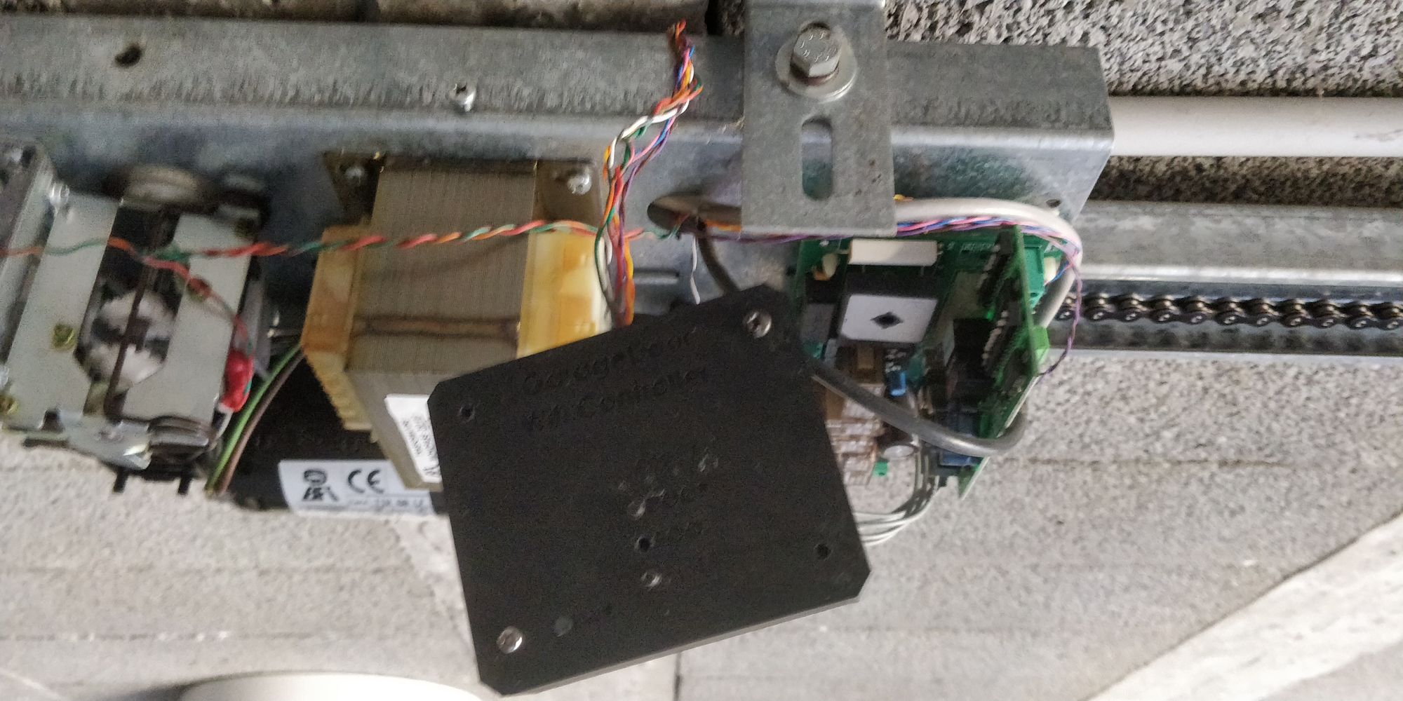
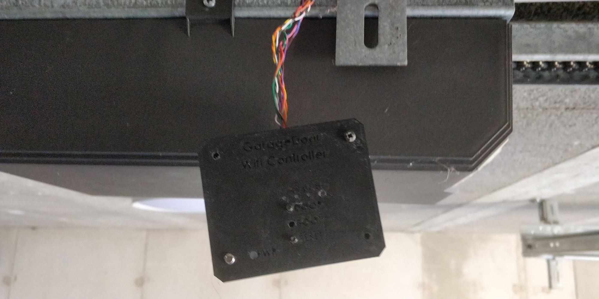
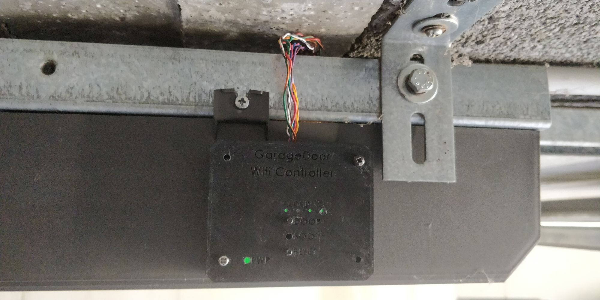
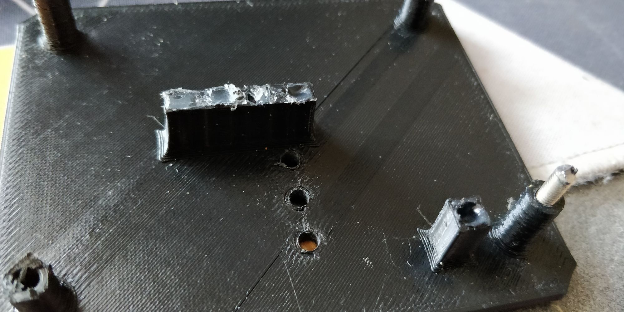
Of course, I can't leave a PCB hanging around on the ceiling, so I modeled a little case that I could stick on the side of the garage door original controller.
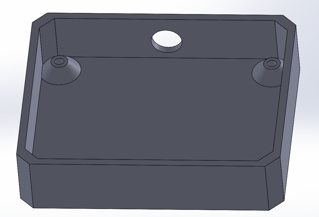
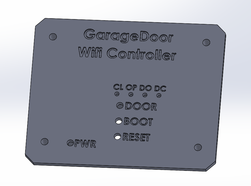
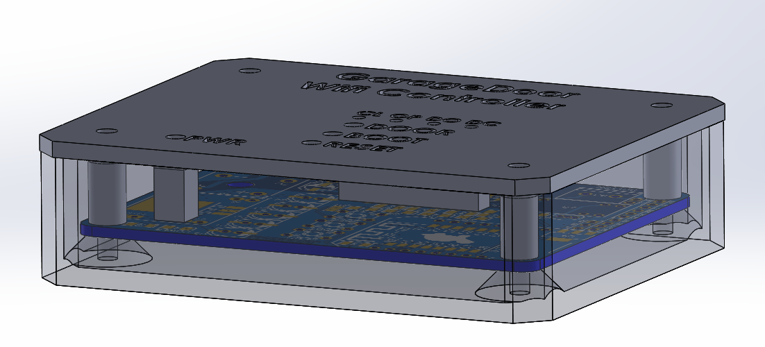
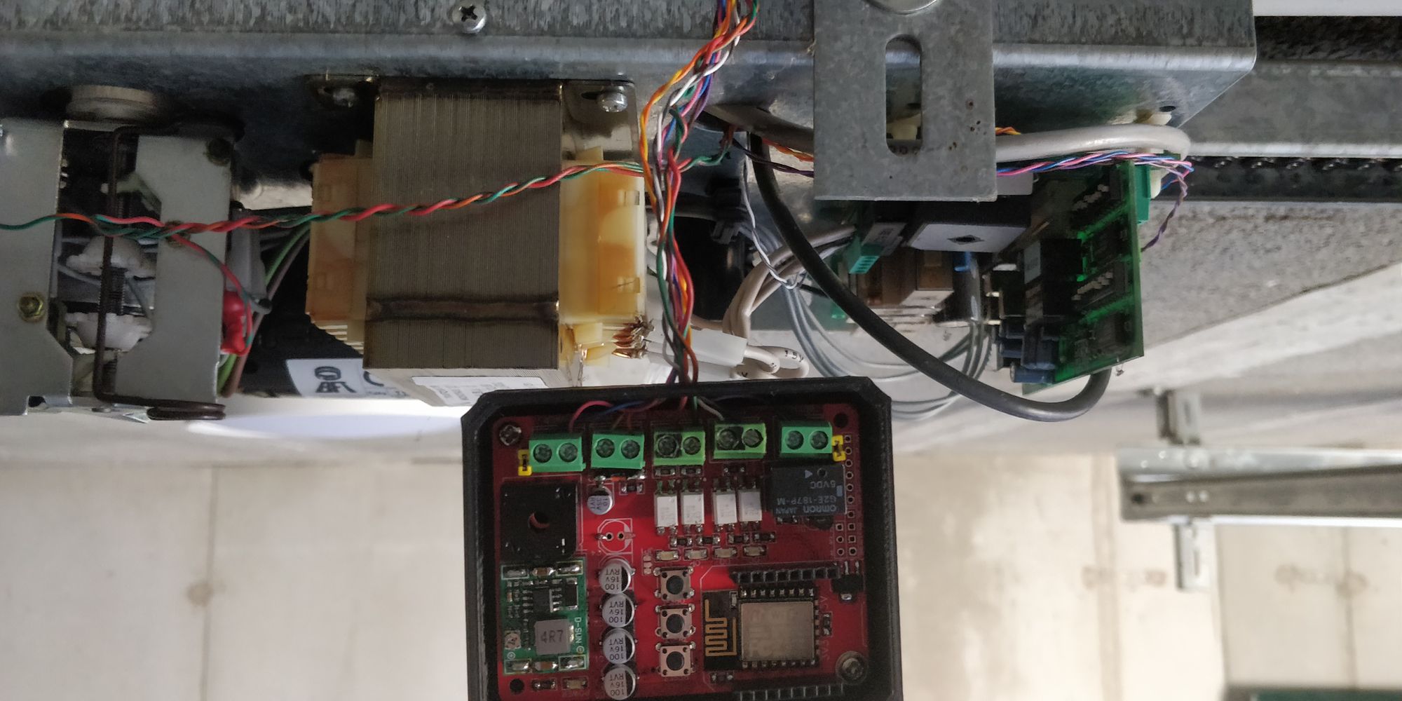
After some "quick" 3d printing I assembled the case and fixed it to the garage door original box.
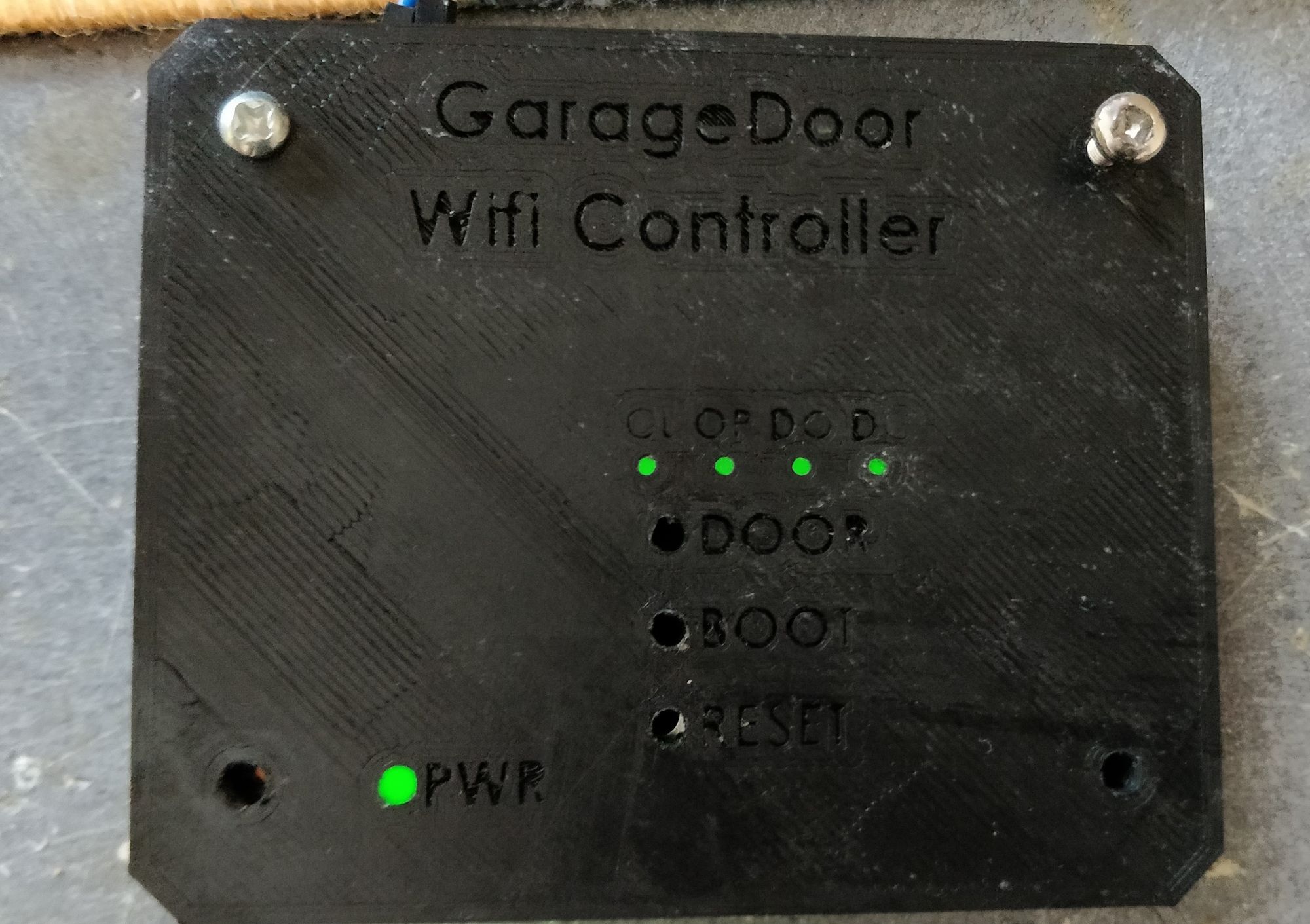
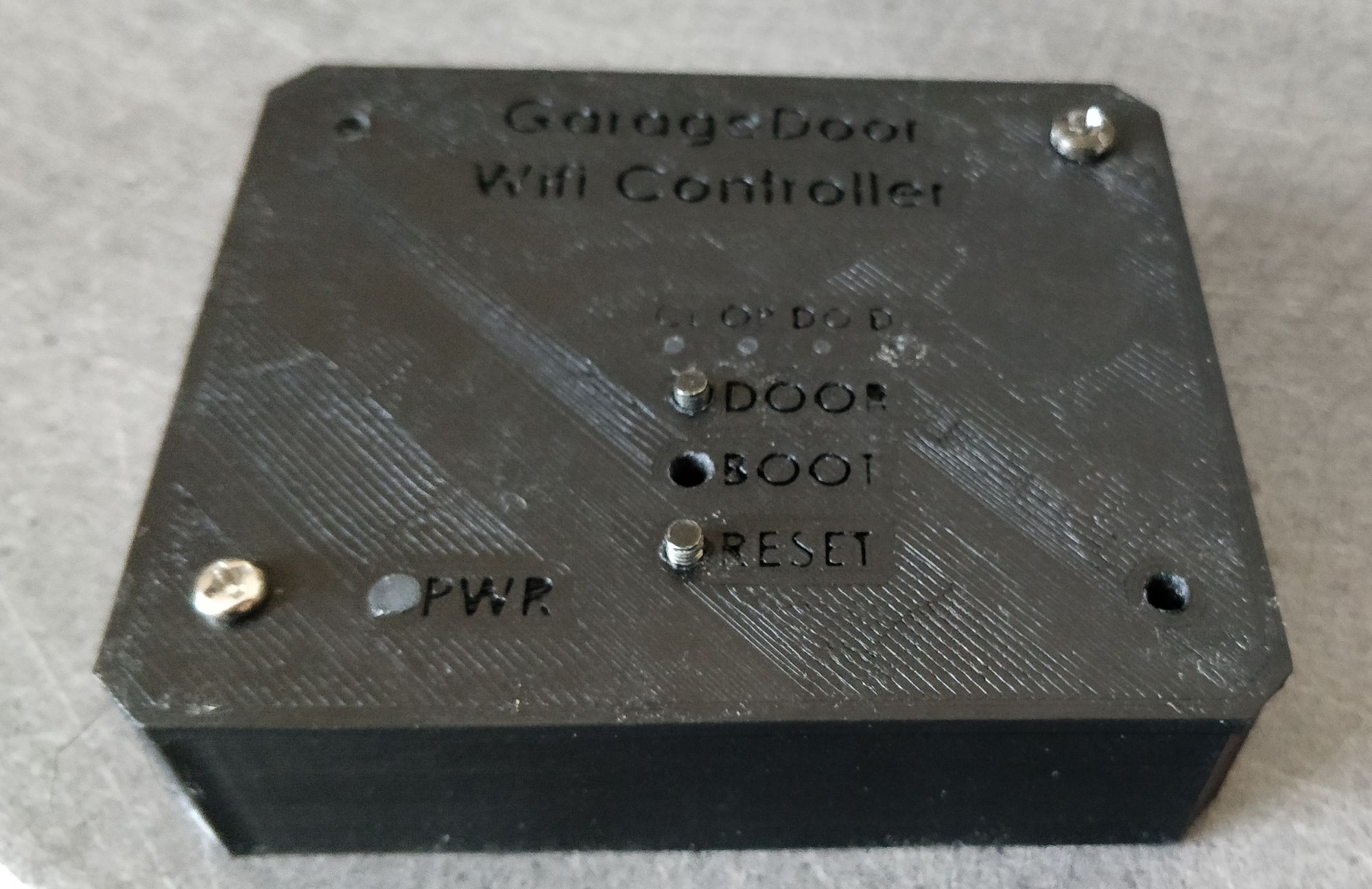
I used some hot glue to act as light pipes and 2 black screw to extend the buttons soldered on the PCB
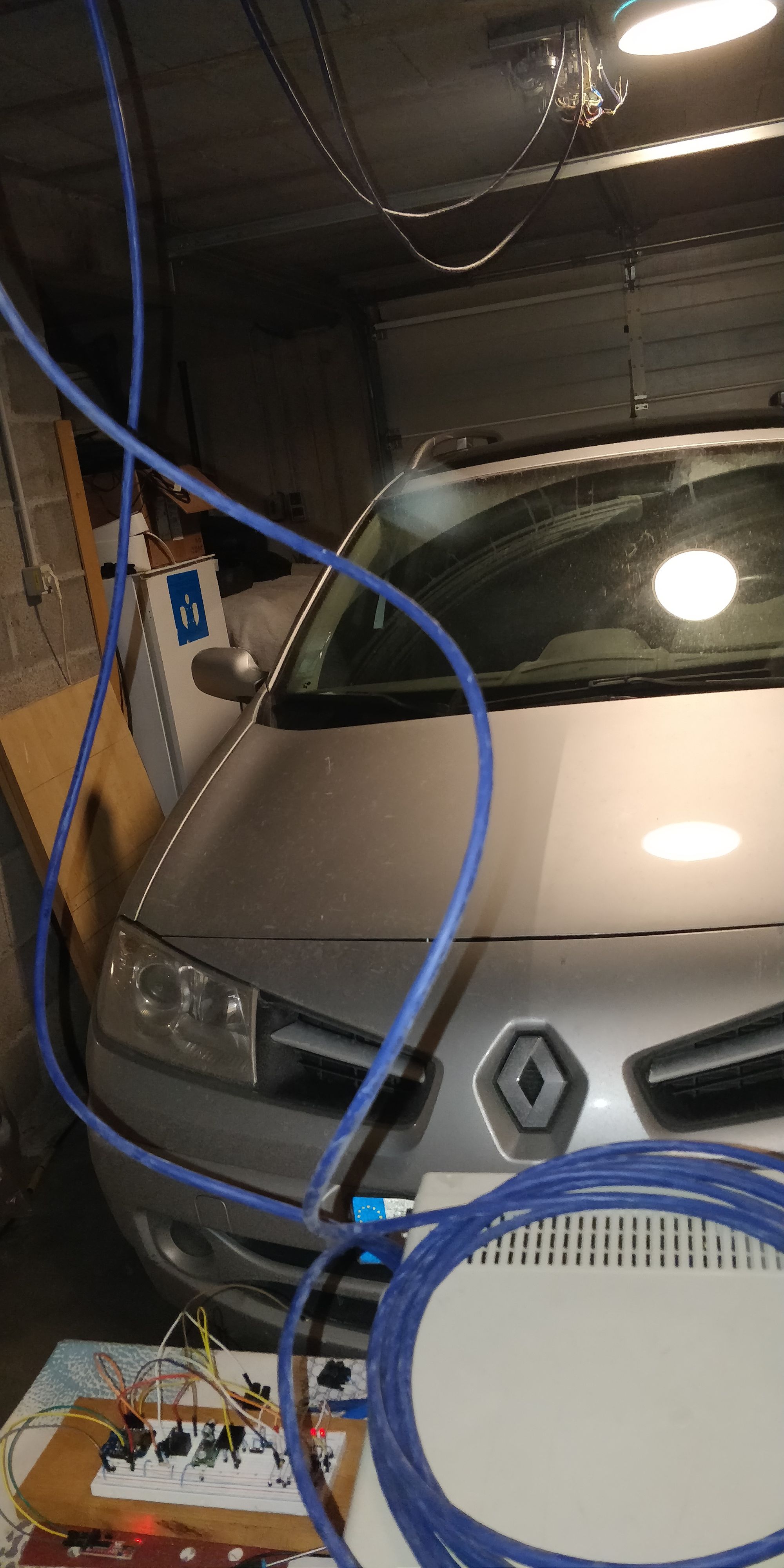
And here is a little demo video of the whole system


Arduino's code / 3d files / schematic / PCB: https://github.com/TheStaticTurtle/GarageDoorController
Garage door documentation: https://www.bft.cz/privat/navody/poh_sekcni/en/TIR 60-120.pdf
Again, thanks to pcbway for letting me try out their PCB manufacturing for this project.
Want to chat about this article? Just post a message down here. Chat is powered by giscus and all discussions can be found here: TheStaticTurtle/blog-comments