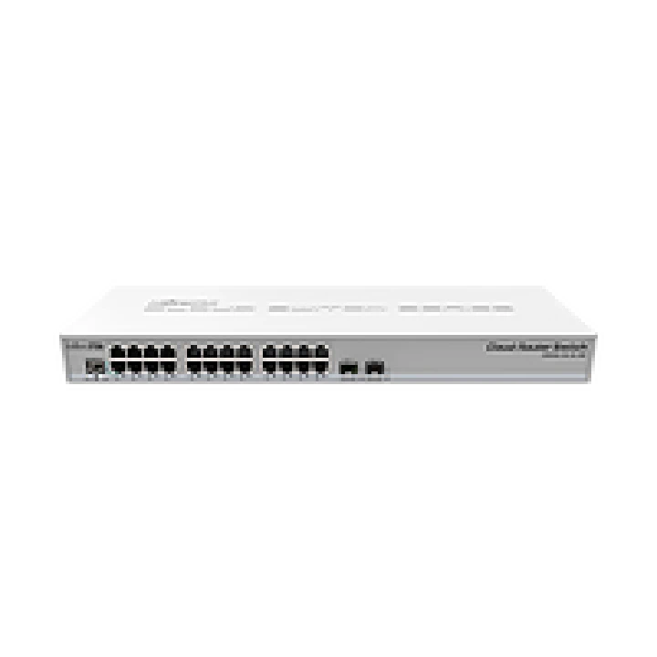
Recently, I bought some used mikrotik CRS326-24G-2S+RM These switches are remarkable 1g switches for the price, but they have one flaw: they use an external power adapter So, I decided to add an IEC C14 connector to it.
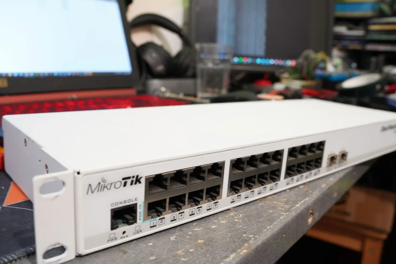
Recently, I bought some used mikrotik CRS326-24G-2S+RM
These switches are remarkable 1g switches for the price, but they have one flaw that some sysadmins consider a pretty big one: they use an external power adapter
Mikrotik also has the same version which is a bit smaller and not rack mounted (the CRS326-24G-2S+IN) which makes me think the motherboard in the rack mounted version is the same 😅
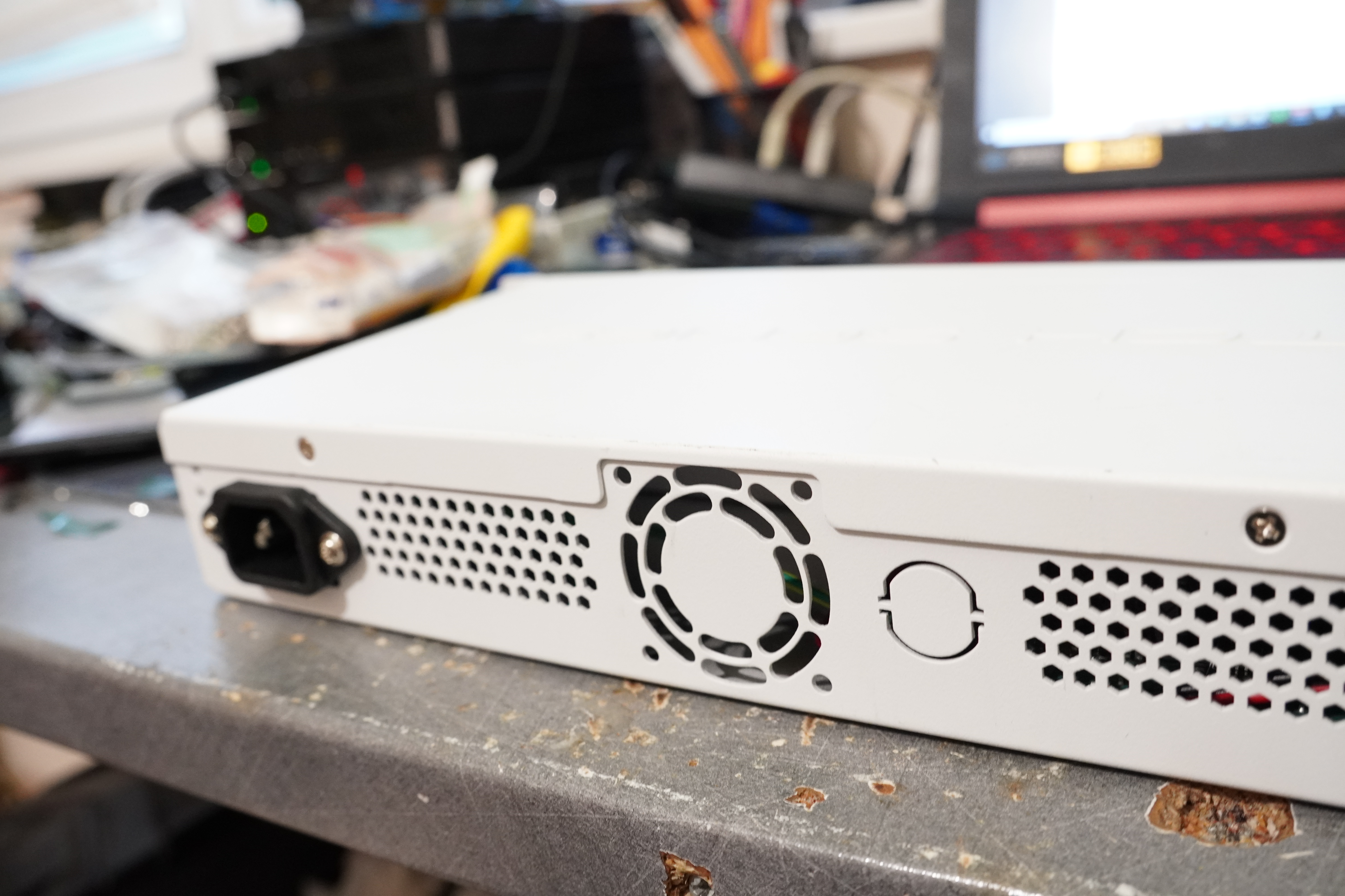
The back of the switch has an IEC C14 cutout in the metal, it's like one of their engineer knew someone was going to do this 🤣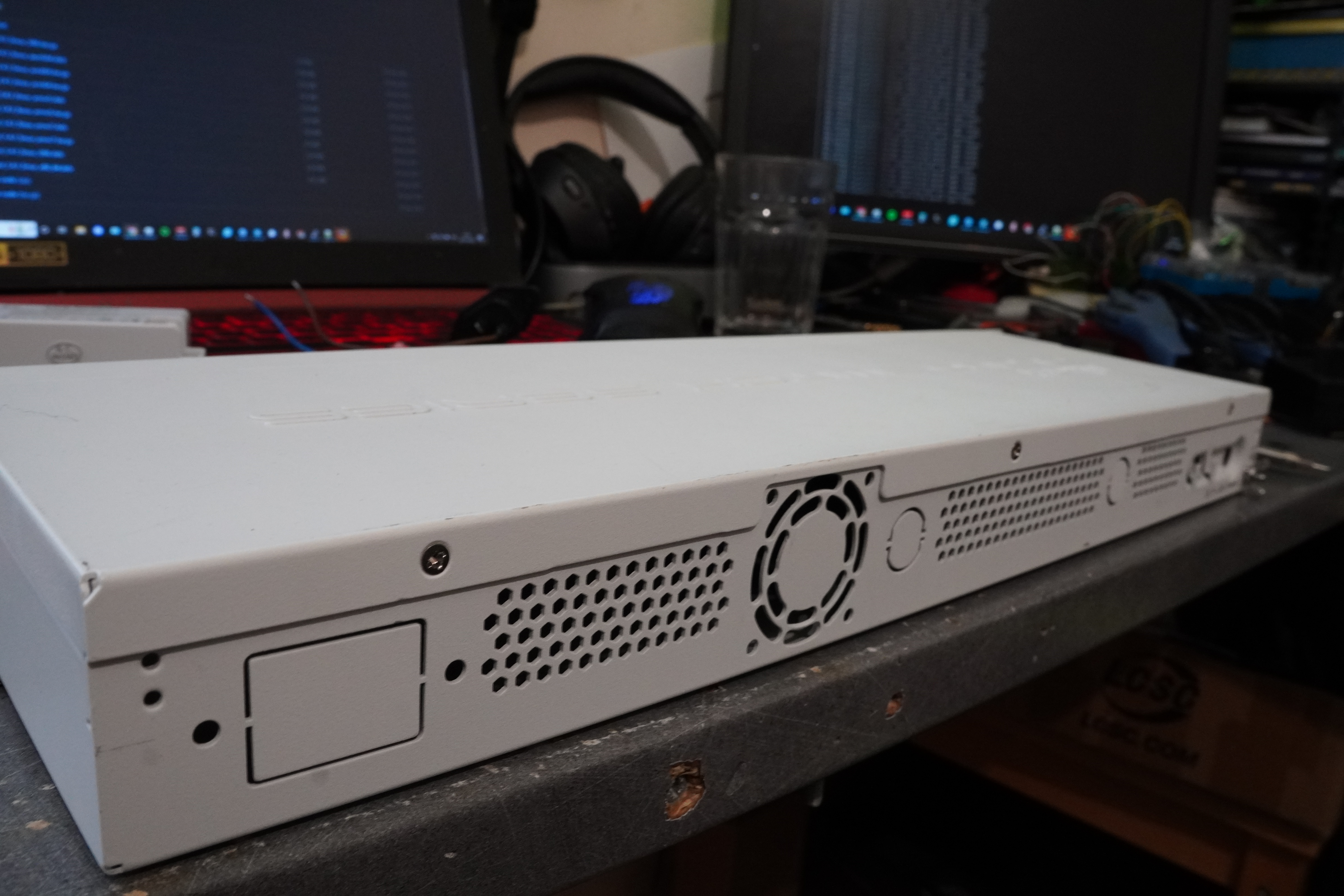
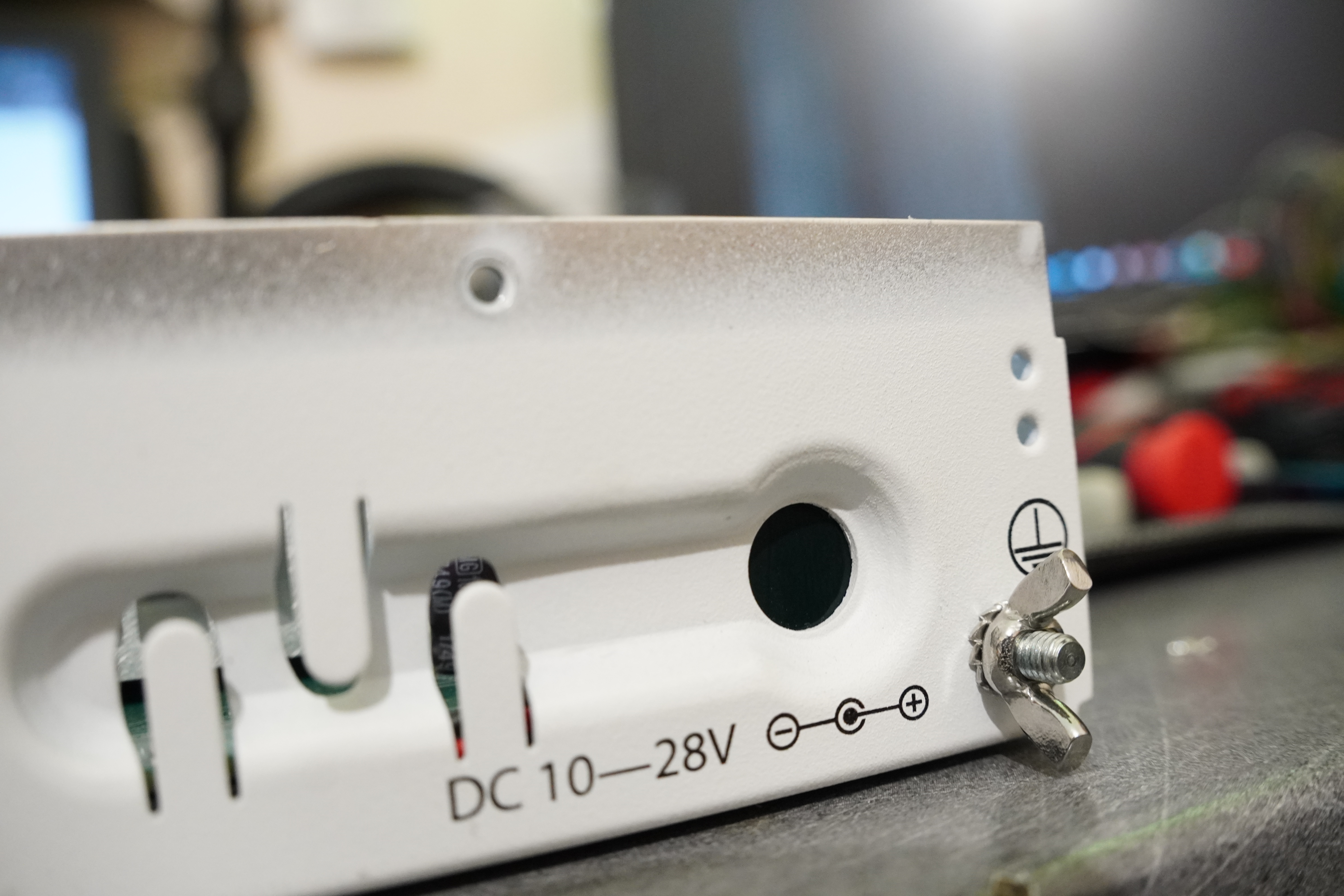
The power adapter itself is a 24v 1.2amp one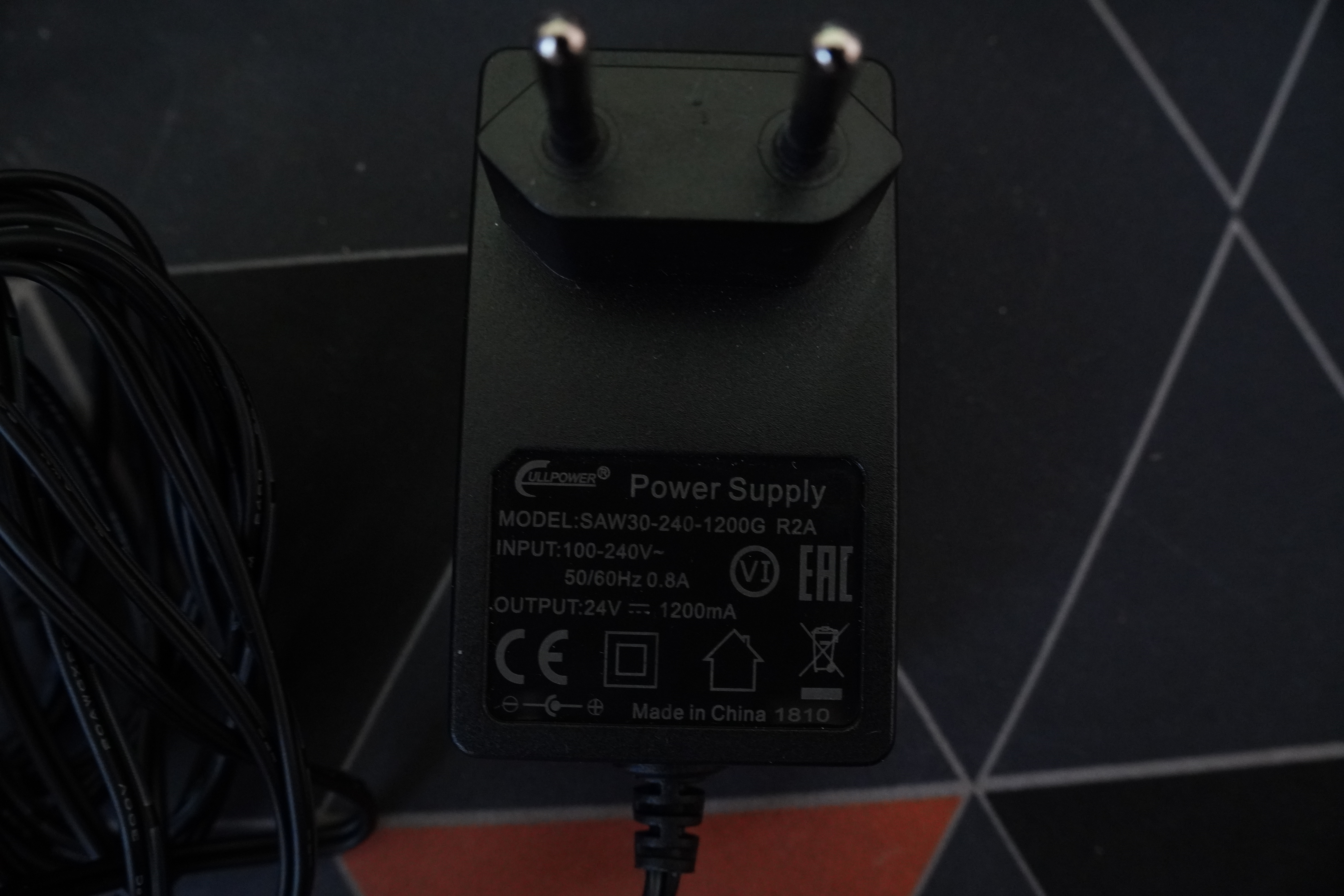
Adding the IEC C14 connector was a no-brainer really, I only needed the connector and power supply.
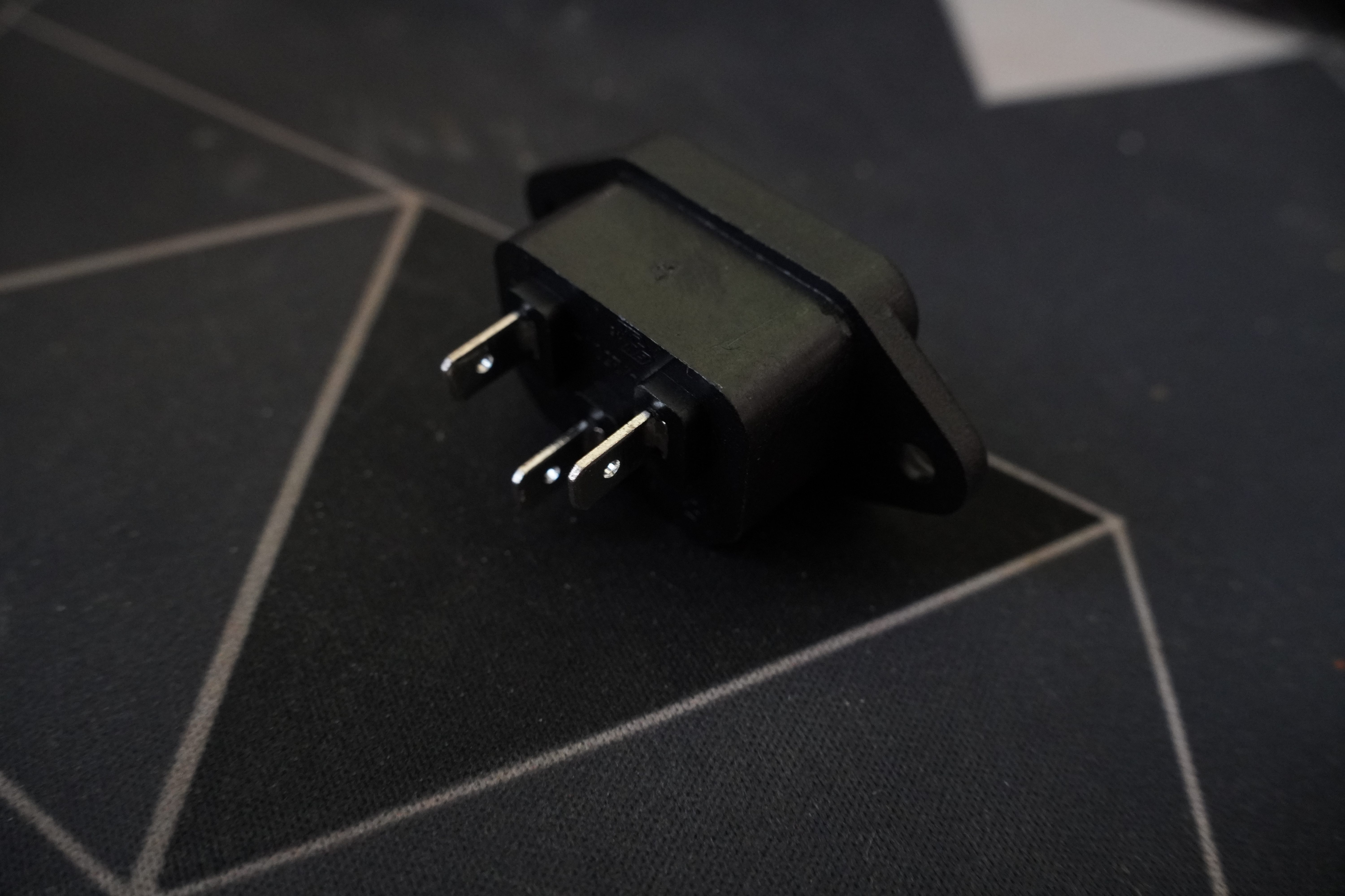
After a quick Amazon search, I choose this adapter, mainly because it matched the original one pretty well and was the fastest delivery one: https://www.amazon.fr/gp/product/B08P8S4SY6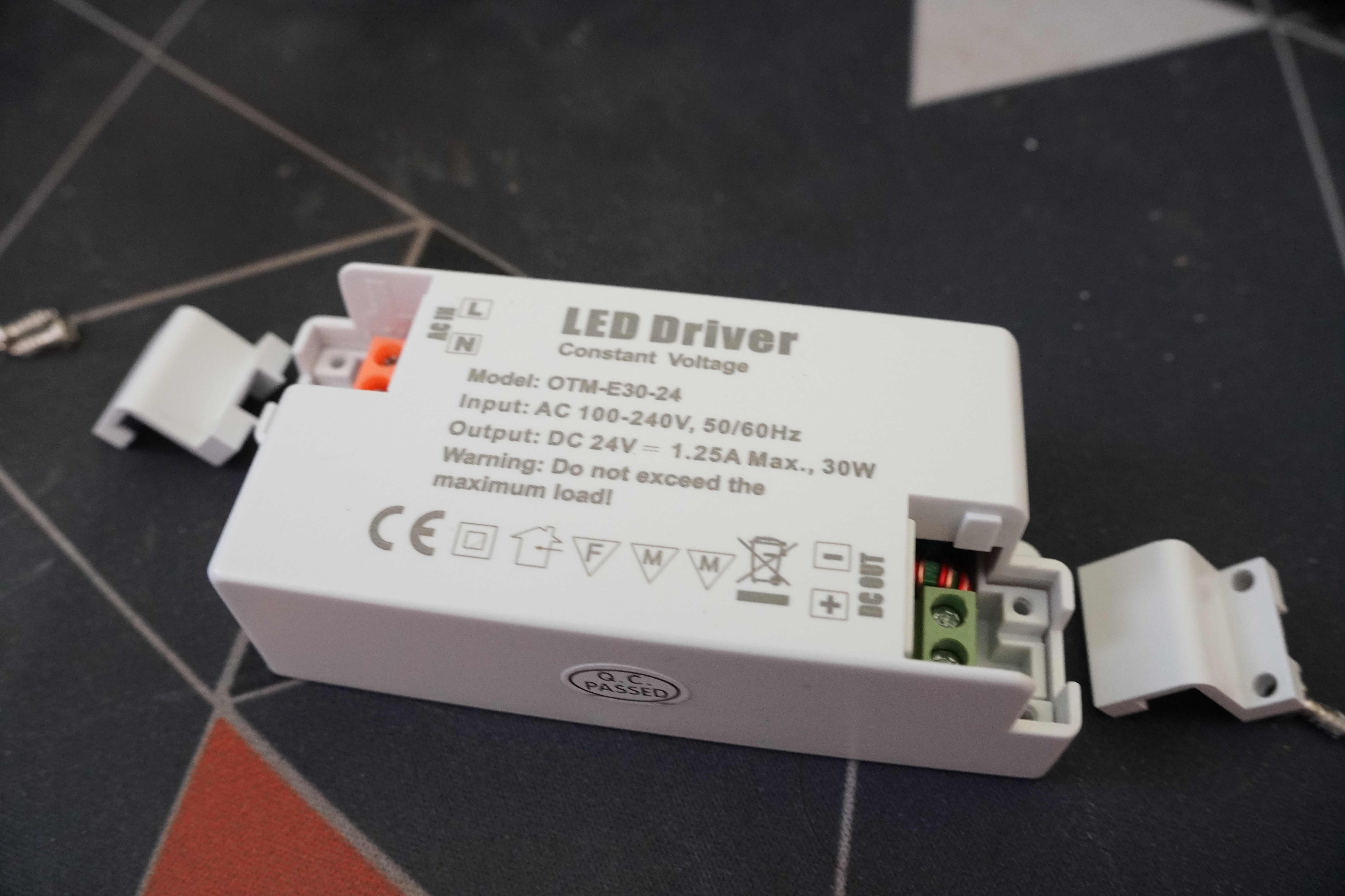
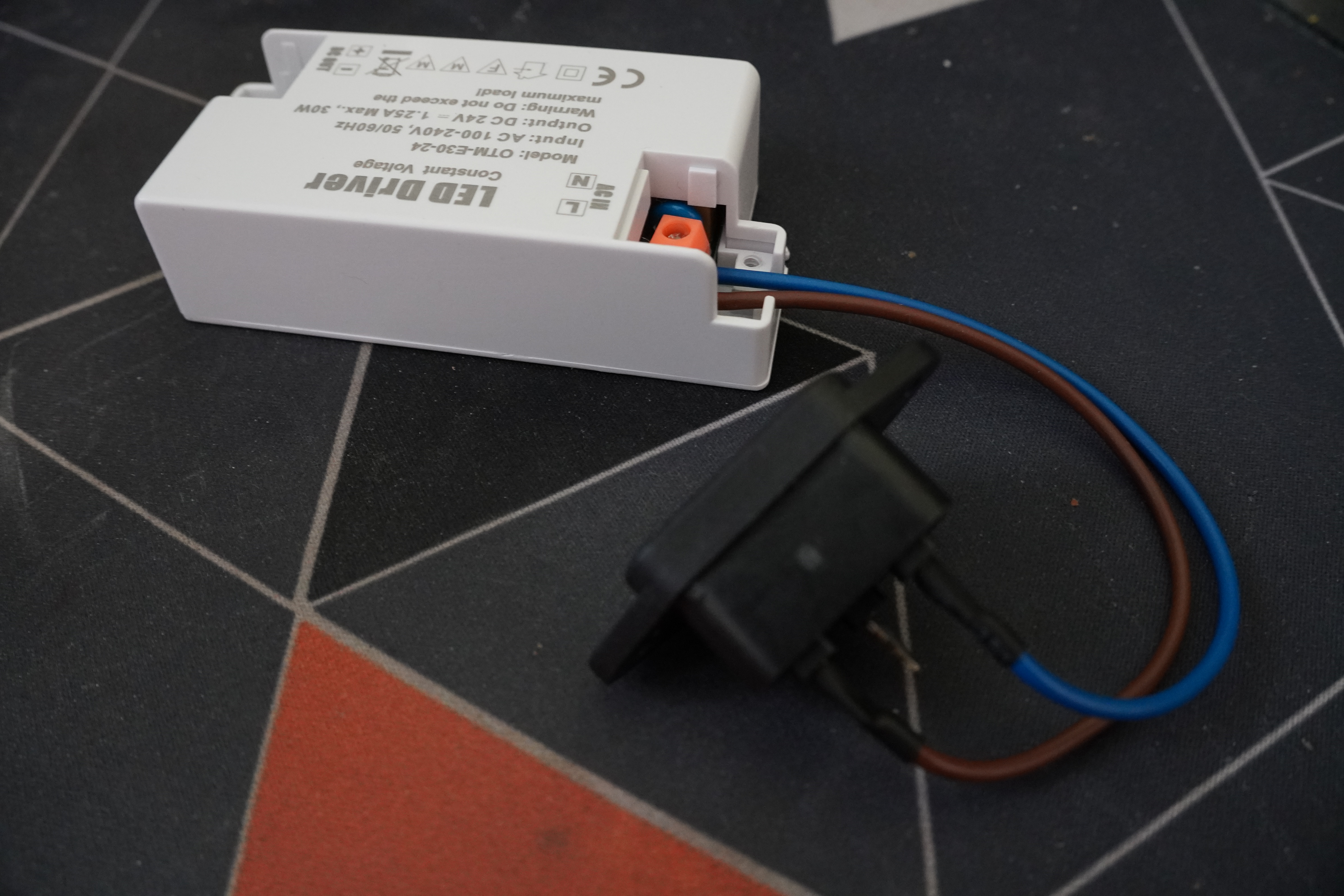
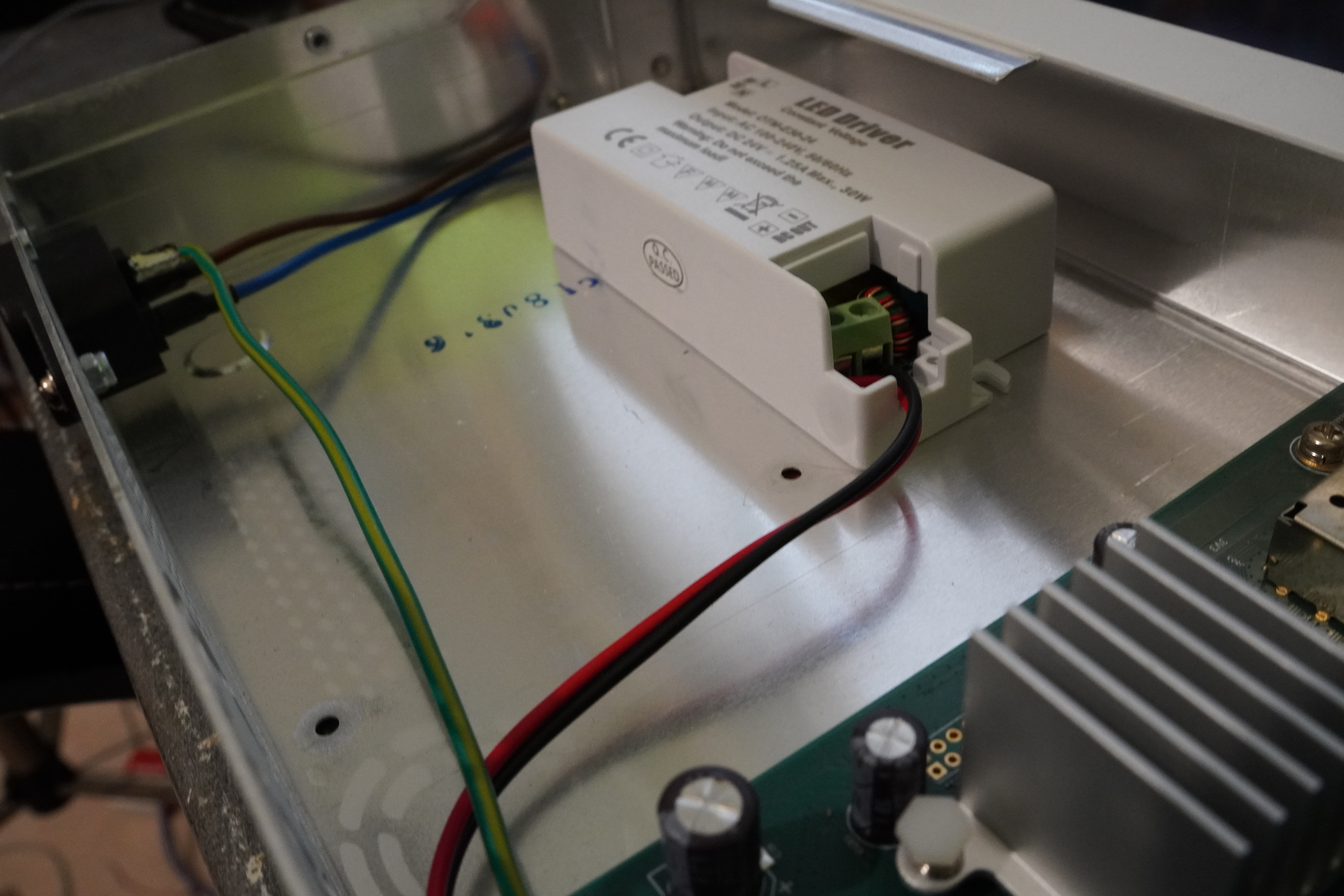
I got some wires from an old 220v cable, soldered them to the C14 connector added some heat shrink and screwed the other side to the power supply input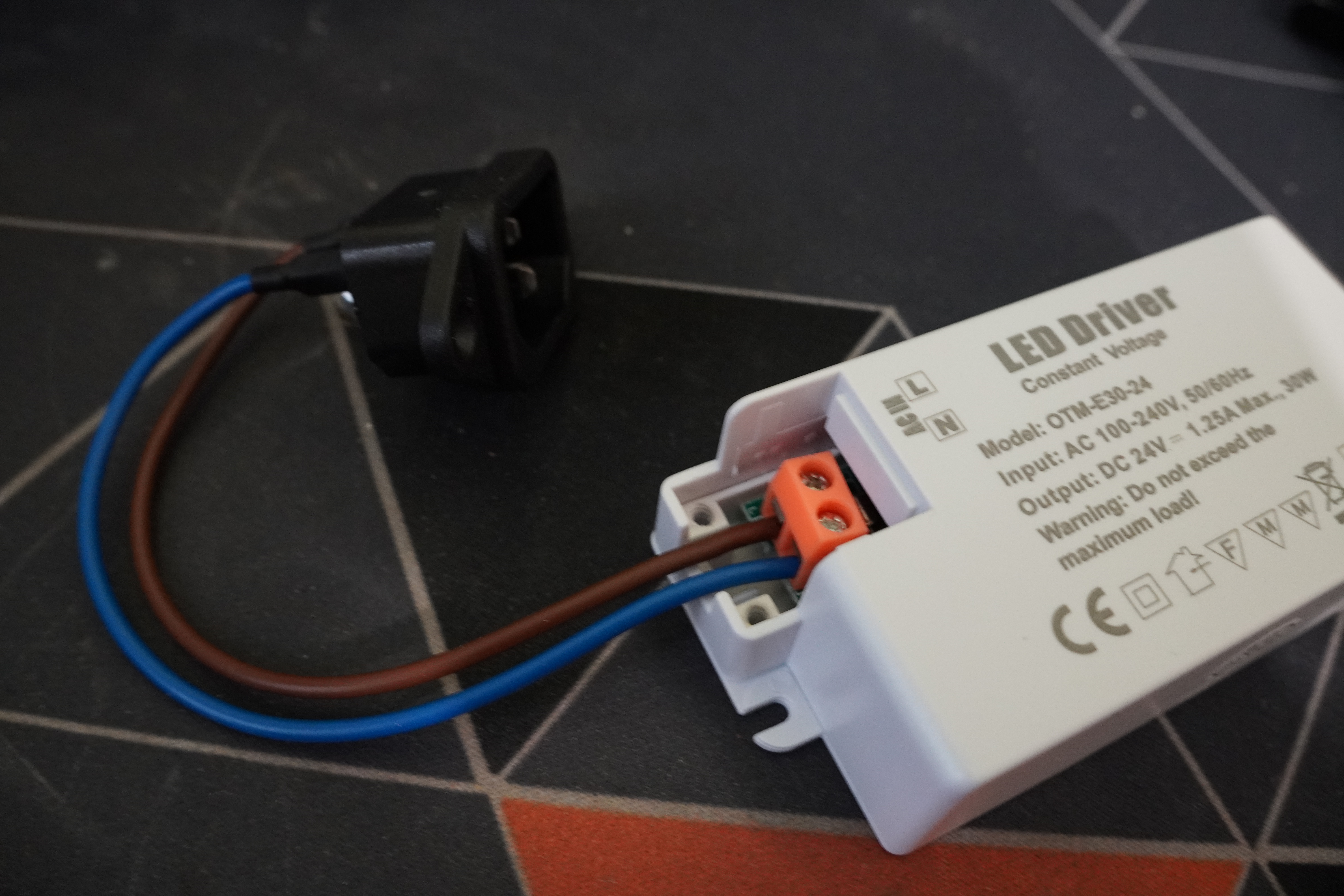
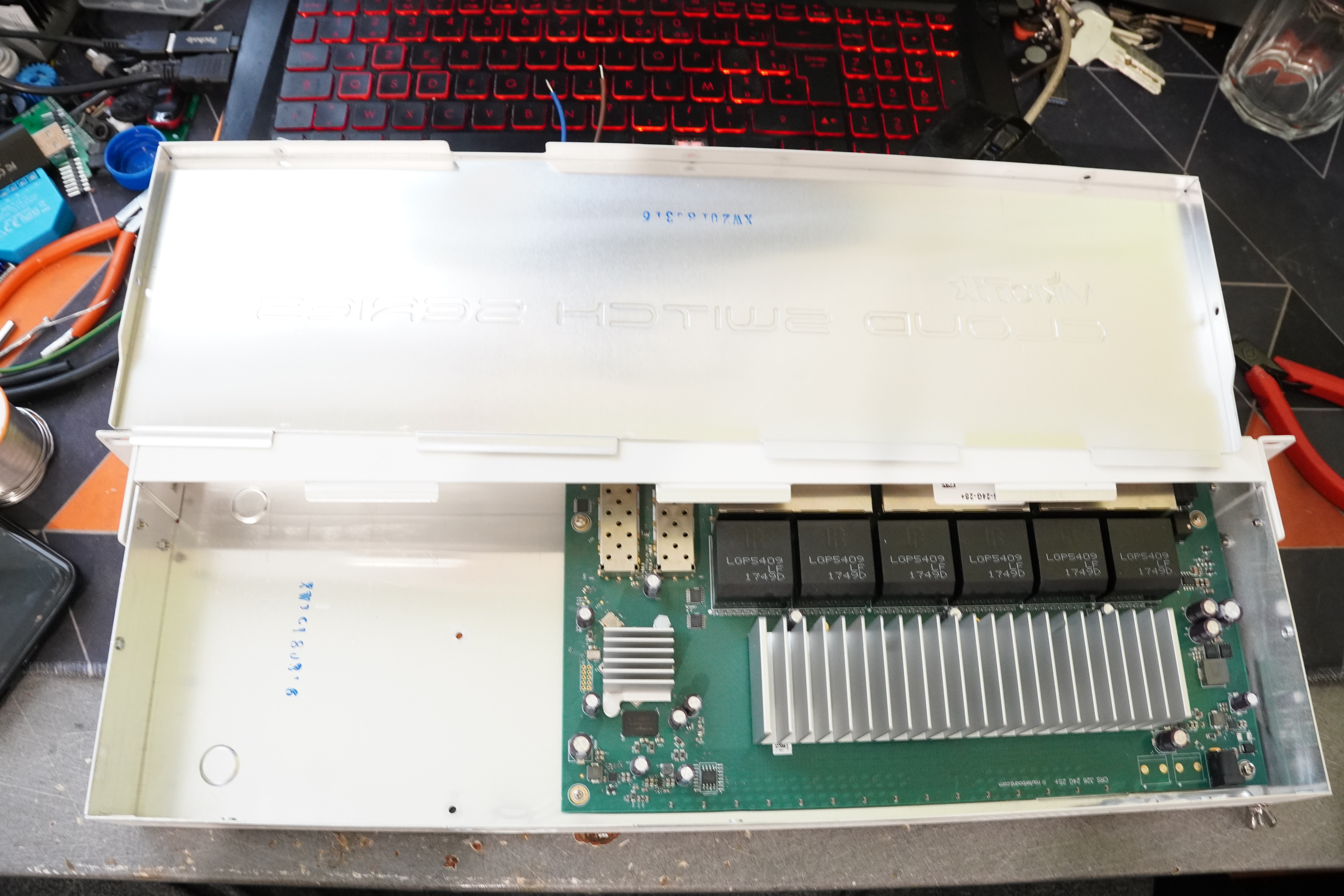
As I predicted, 1/3 of the case is empty, leaving more than enough space for the power supply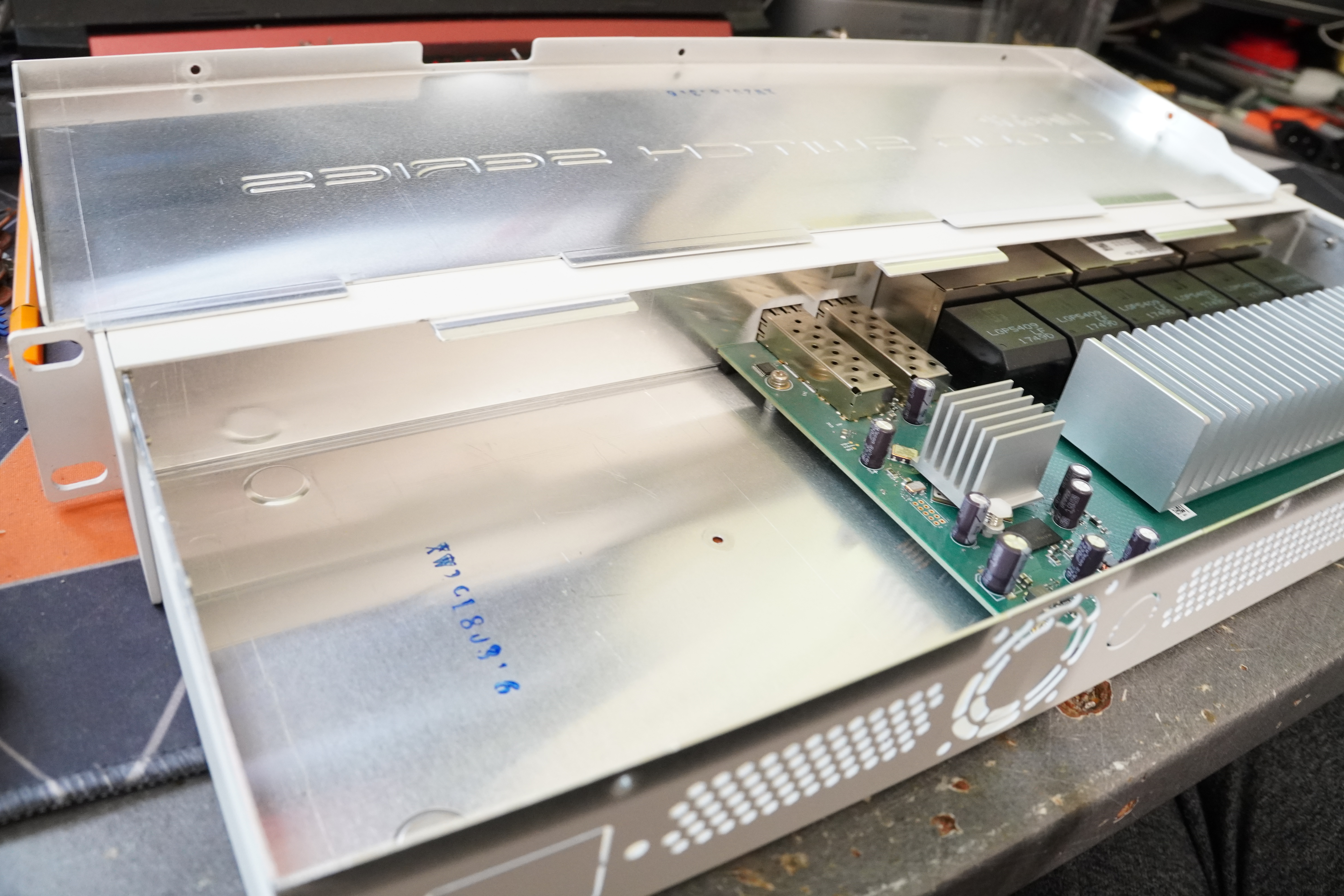
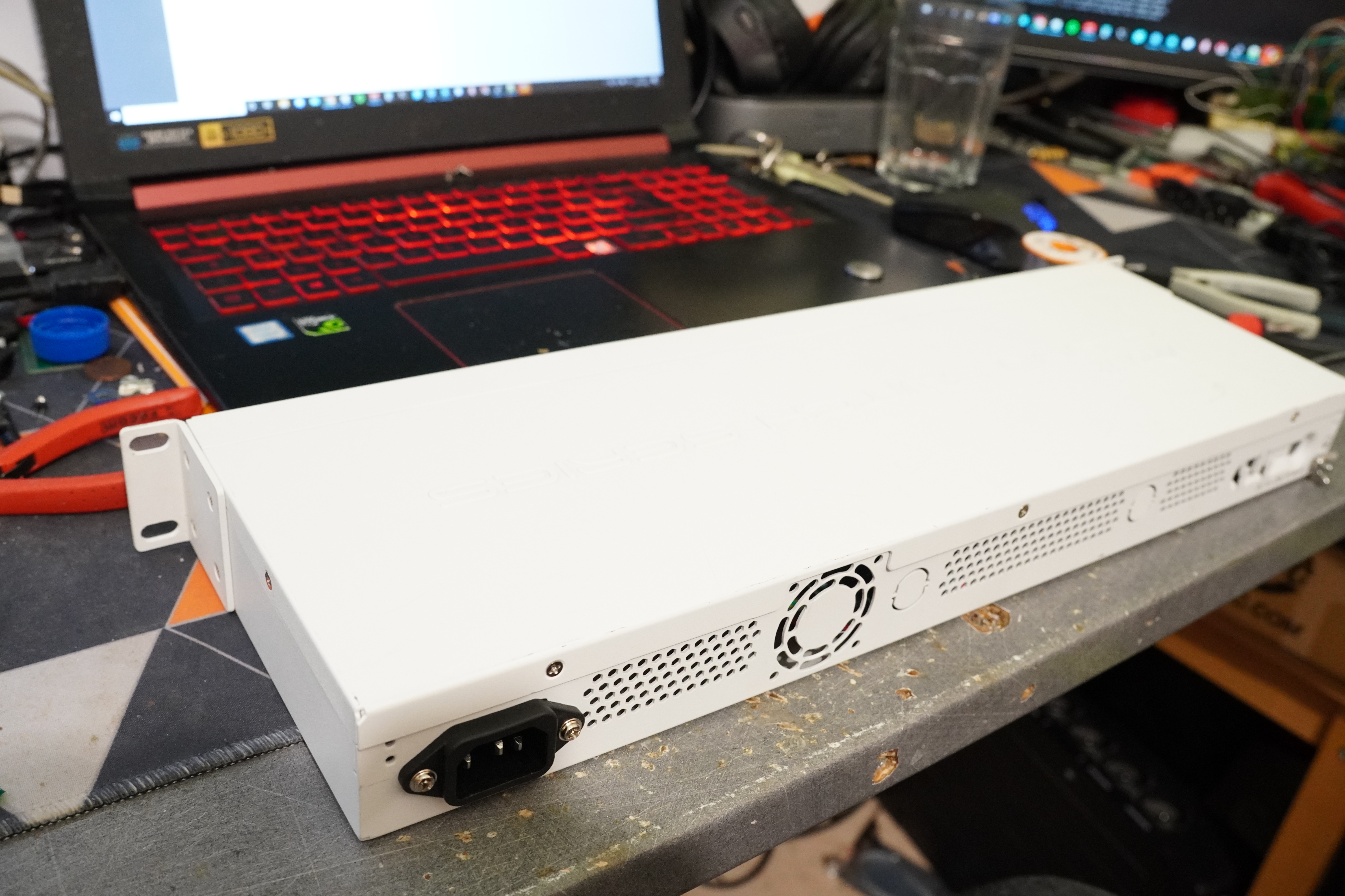
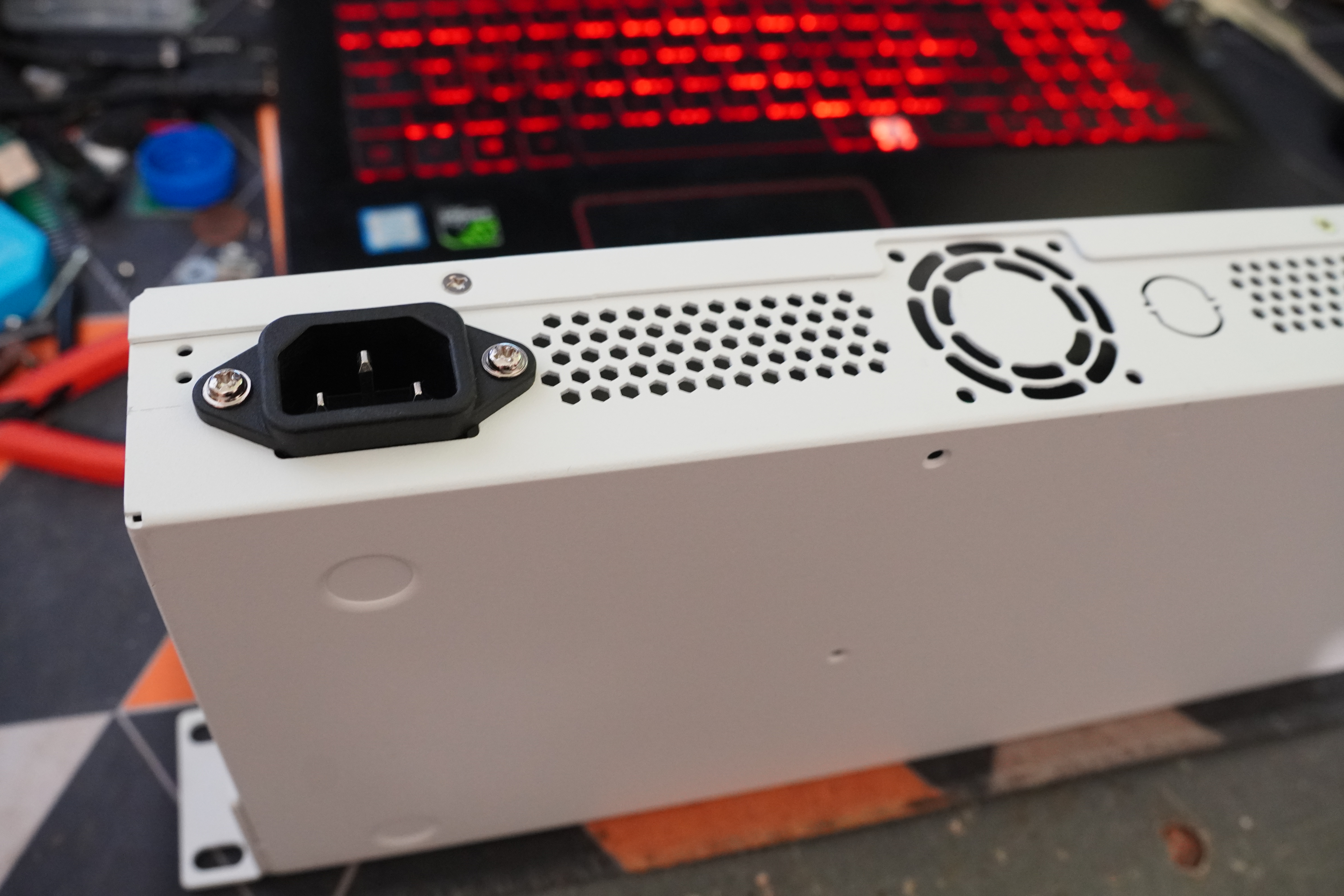
So, I went on and broke the little tabs, screwed in the C14 connector and connected the power supply: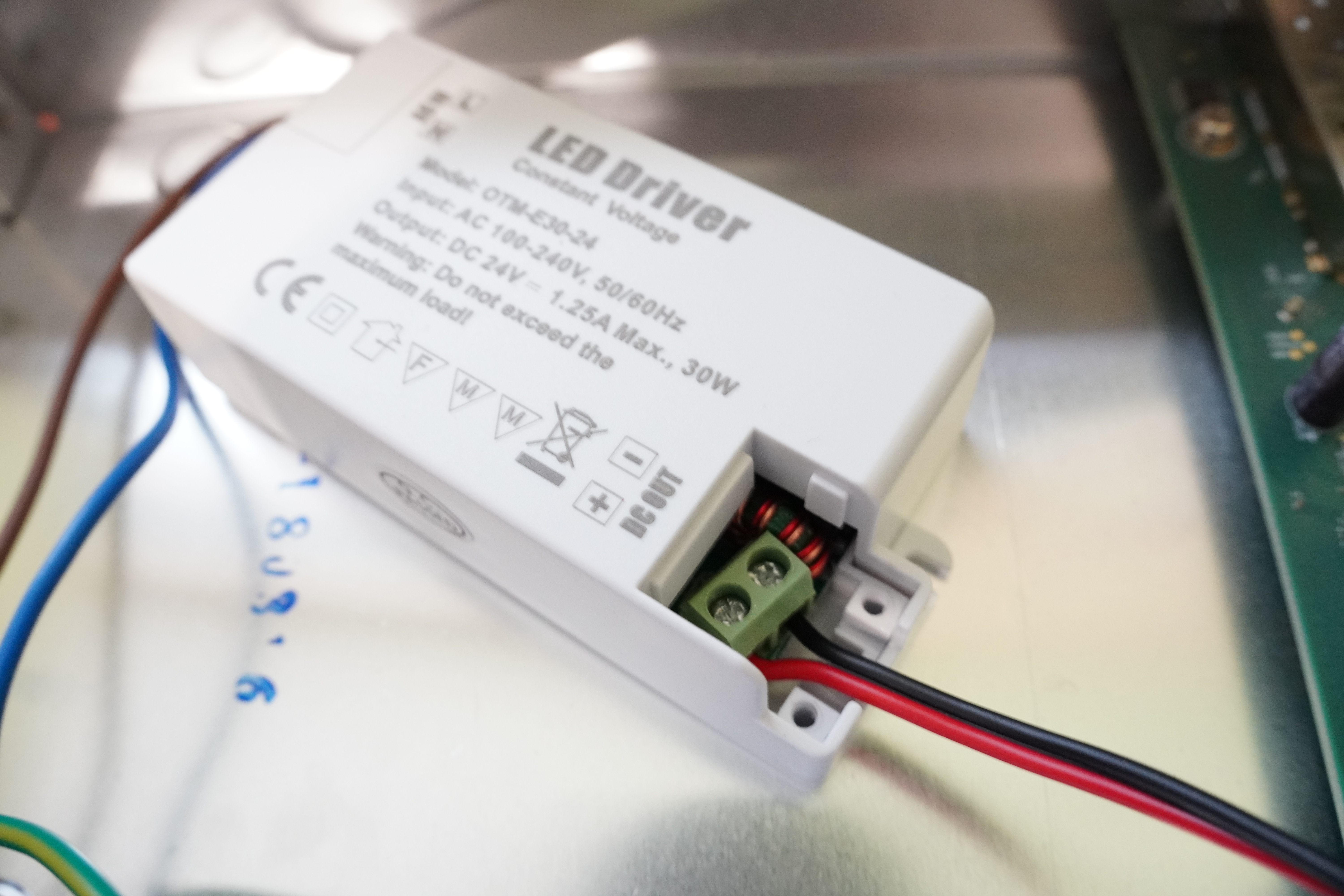
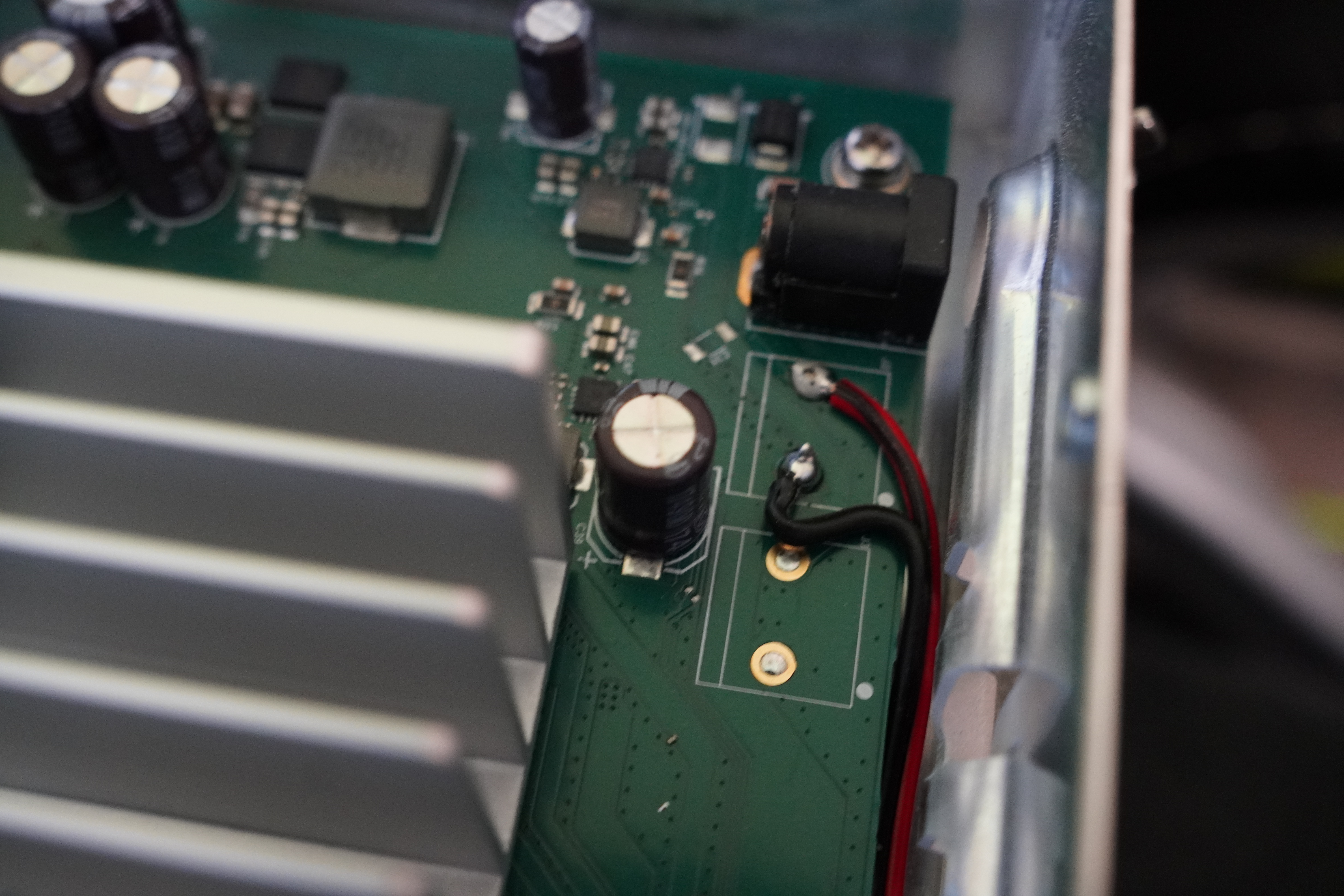
To actually power the switch, I hesitated between soldering straight to the board and making a wire+connector come out of the case. As the switch is already out of warranty, so I decided to solder directly to the board.
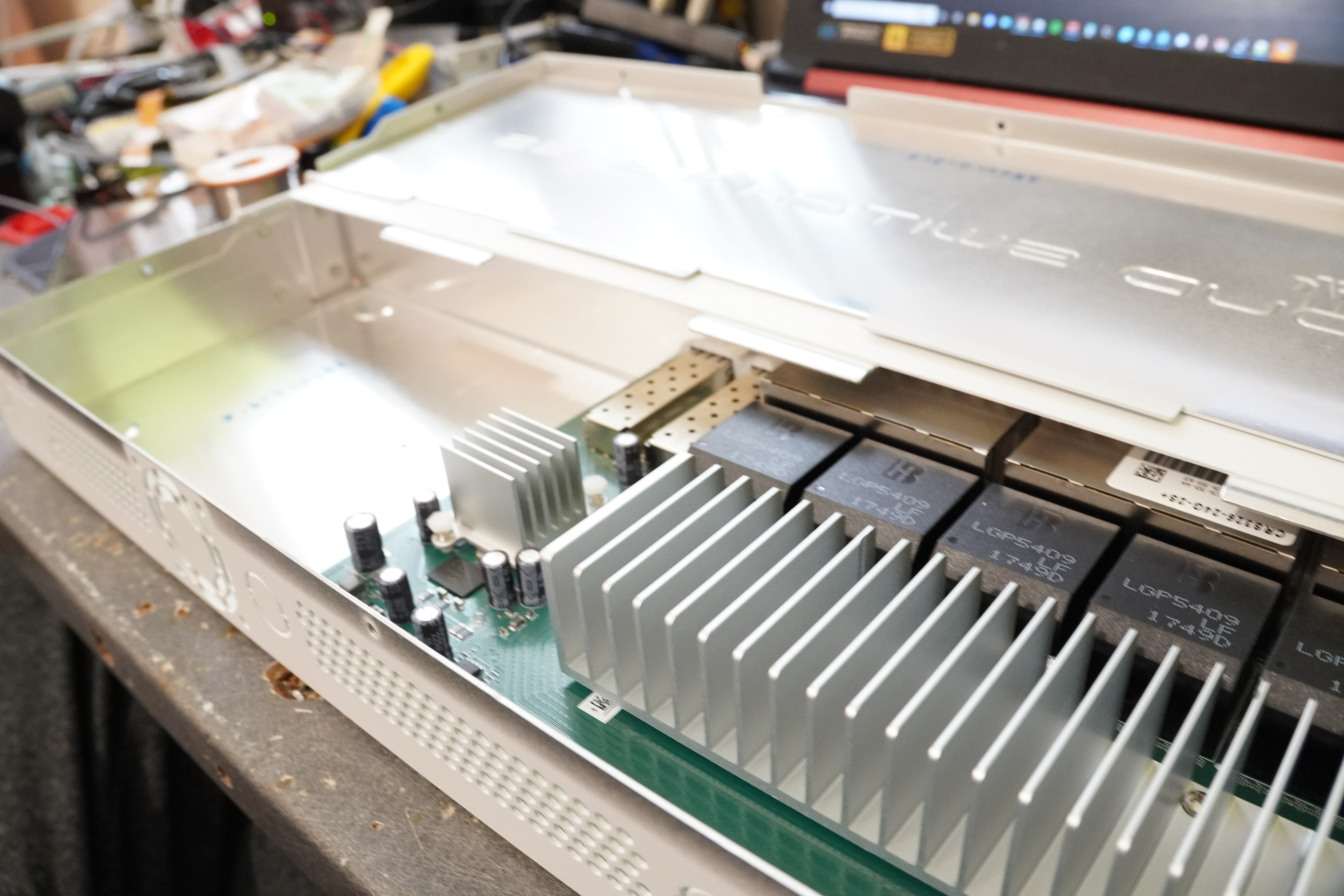
Fortunately, the PCB has some holes that I can use properly instead of soldering to the connector tabs: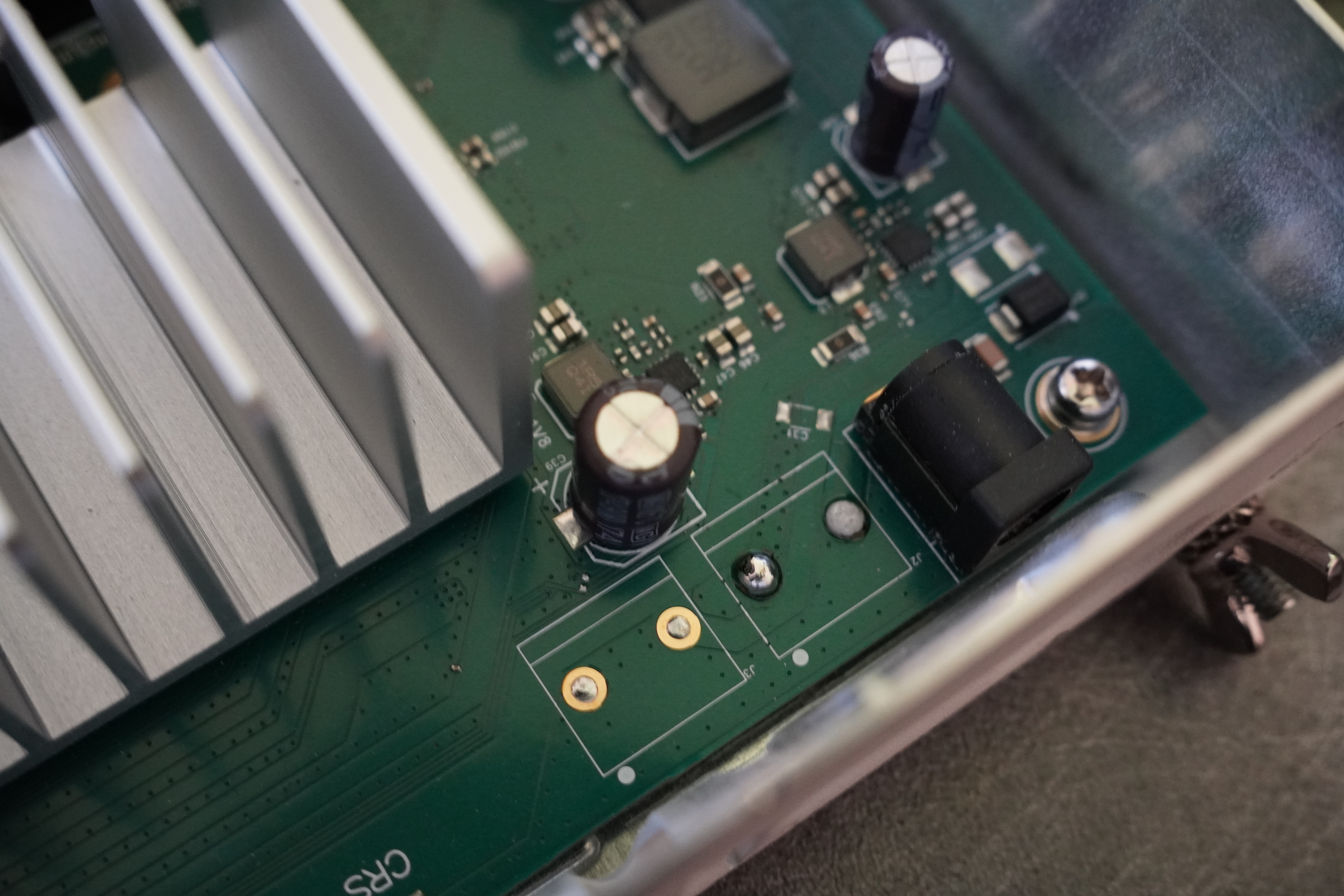
I also added the earth from the IEC C14 to a screw that touched the chassis: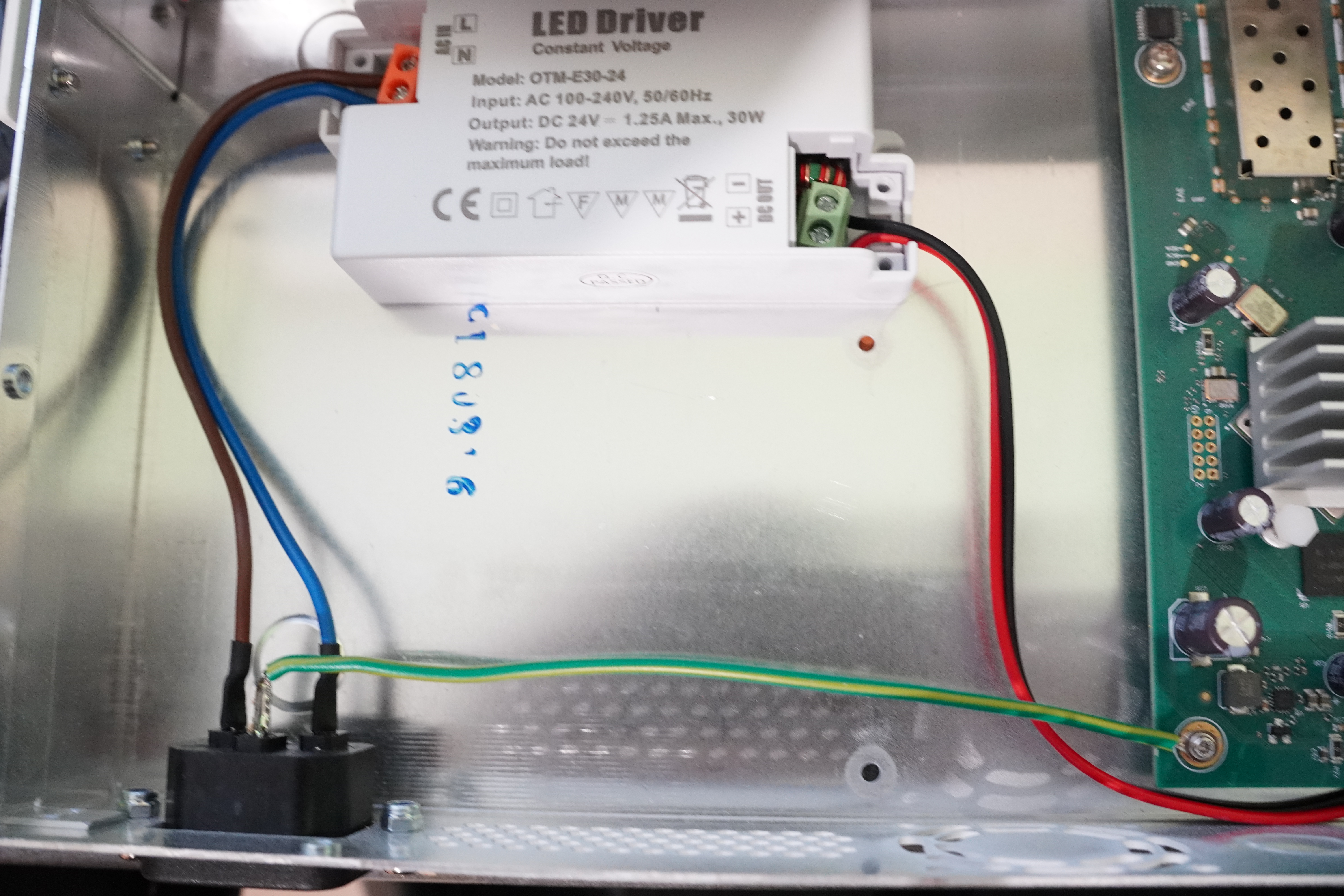
After a quick test to confirm, it still lighted up 🔥 :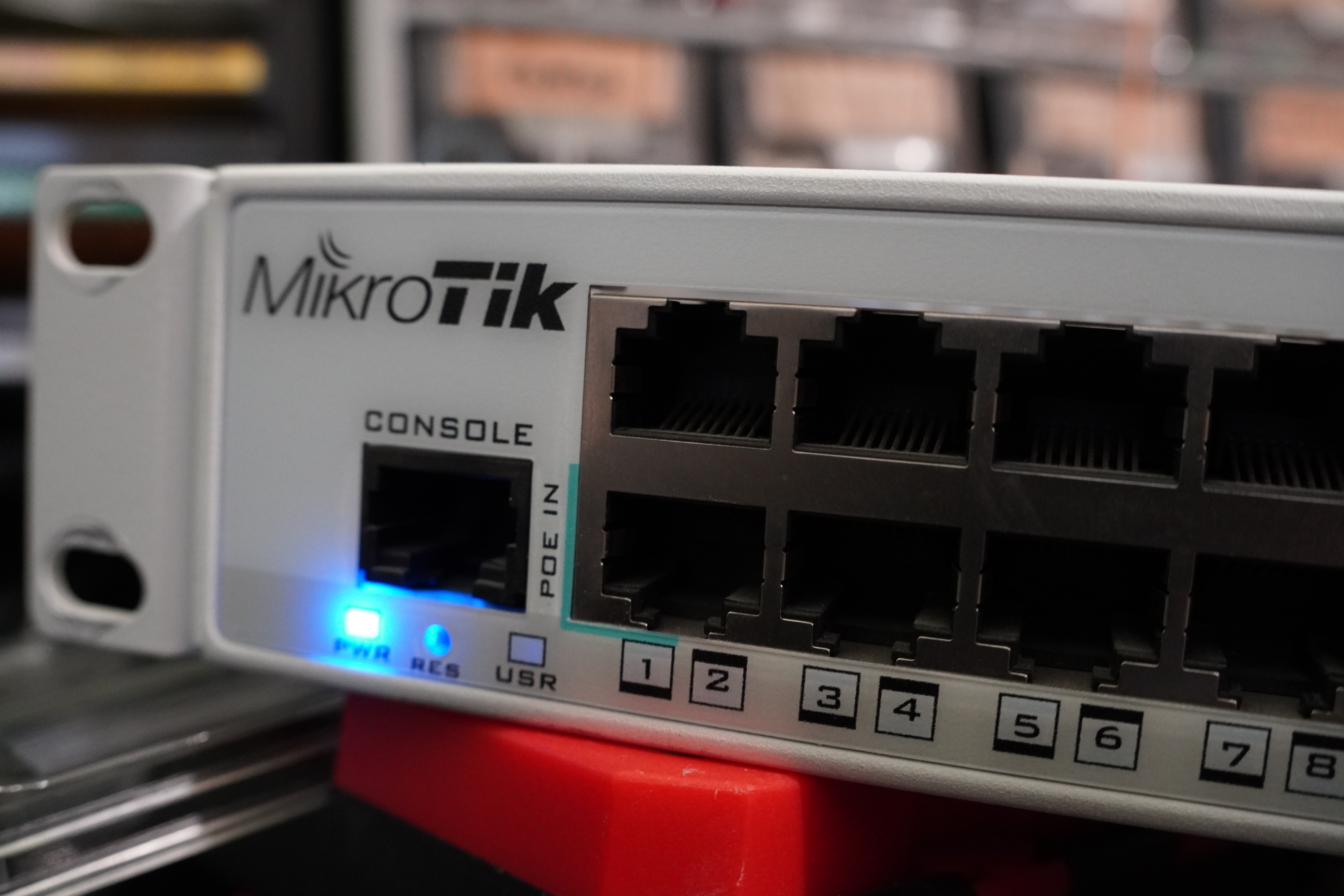
I added a little piece of tape between the original connector and the case so that I wouldn't accidentally power it from here: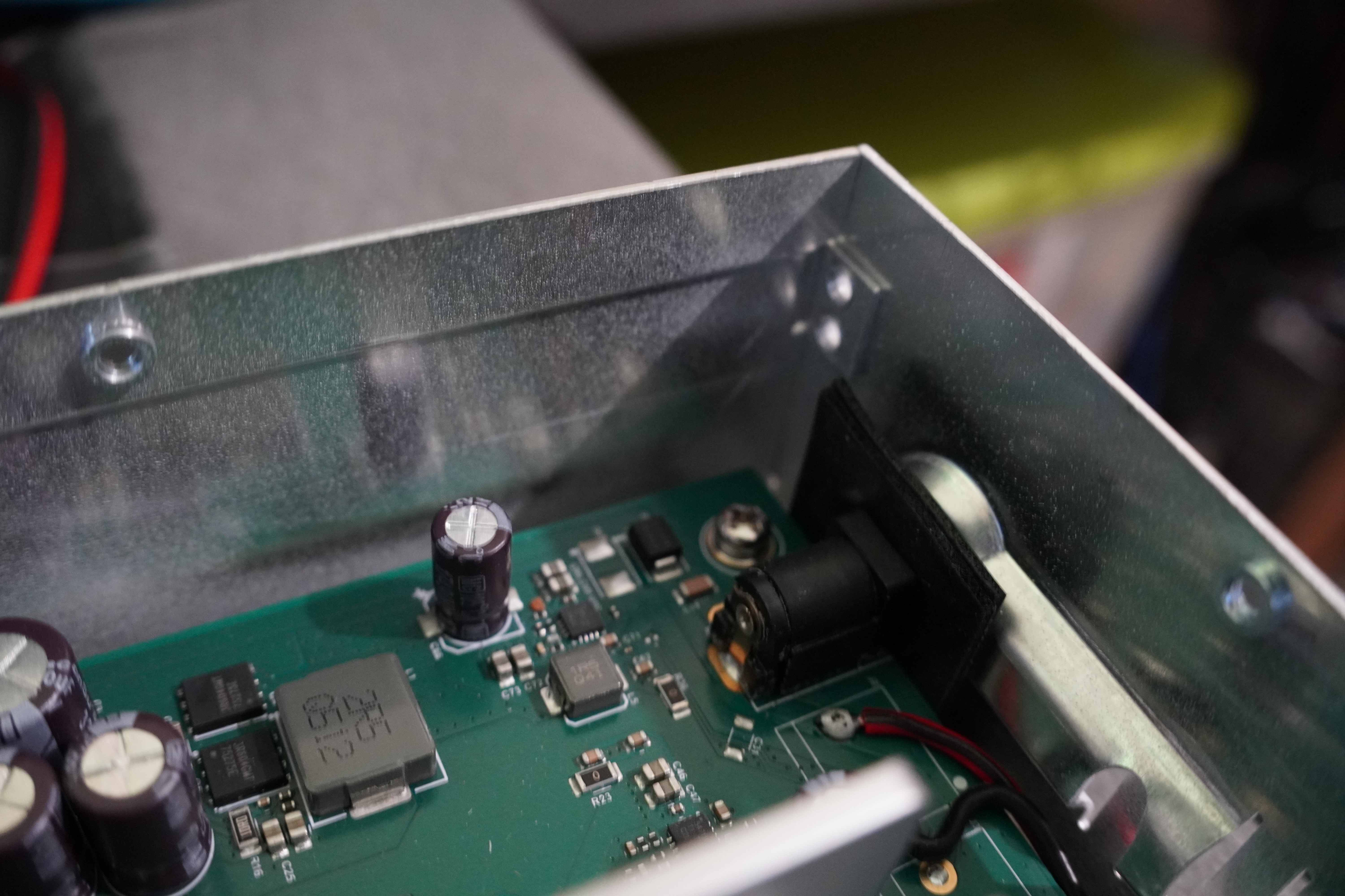
And finally, I closed everything and put it back to work on my desk: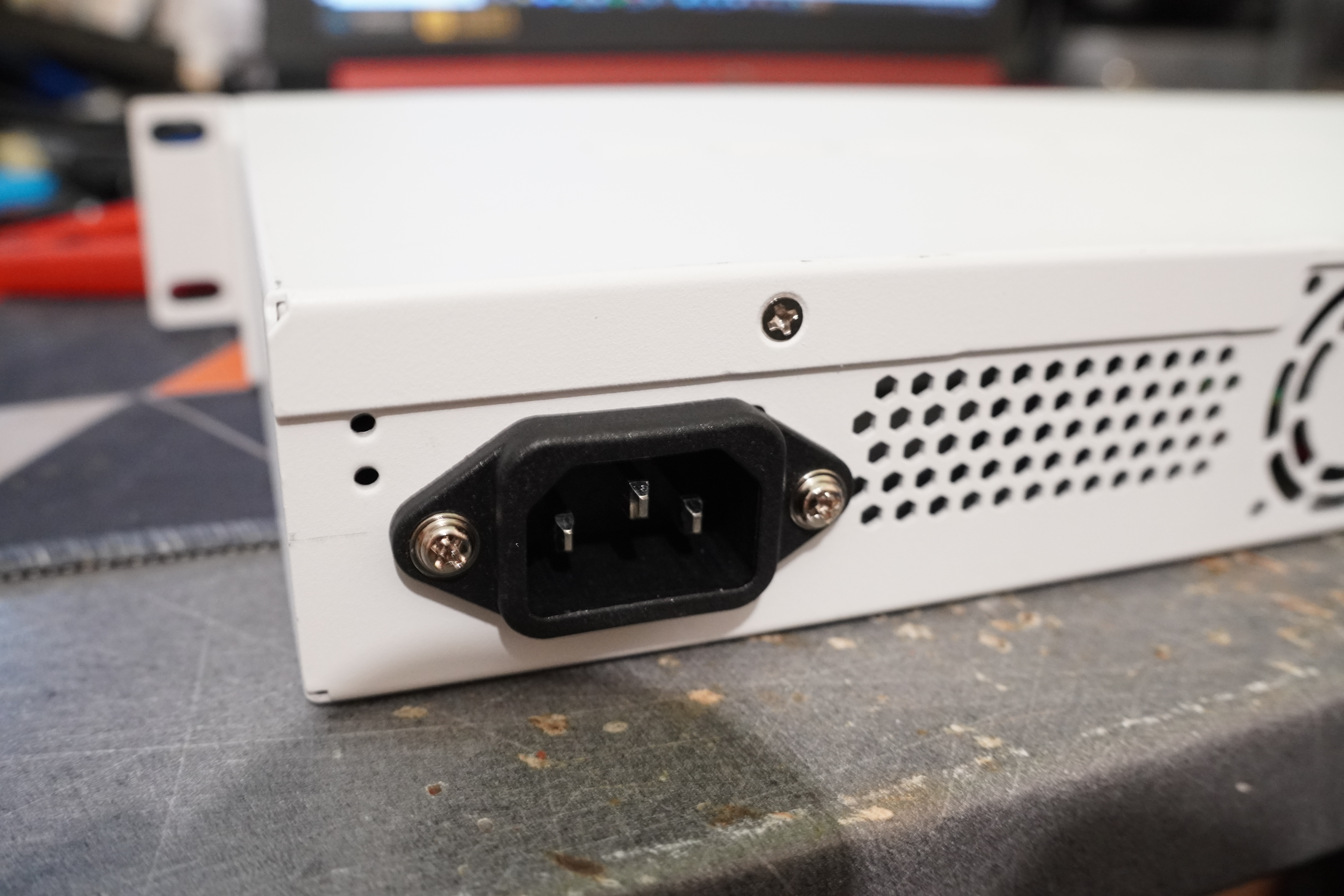
All in all, this is an effortless mod that solves a relatively big issue, and I'll repeat it to the other two switches I own 😄
Want to chat about this article? Just post a message down here. Chat is powered by giscus and all discussions can be found here: TheStaticTurtle/blog-comments